Prototyping a Robotic Vacuum Cleaner.
(C) SnowCron.com
In this tutorial we are going to create a platform that can be extended to become a full scale robotic vacuum cleaner. This particular platform as is will not clean anything: it will move, use bump sensors to locate the walls and turn around to avoid them. However, approaches we use are going to help you in case you need to create an industrial prototype of the real thing.
Don't take me wrong: one can build a device with similar functionality using cardboard and thermal glue. Why do we need any advanced prototyping, 3d design software and so on? Because the cardboard robot is a dead end. Here are the reasons:
- It is not scalable. Now, even with vacuum cleaner, you might want to make it bigger to fit brushes, bottles with cleaning solution and a mop. What if you are prototyping a car? Can you use cardboard? "Cut it with kitchen knife, then bend it to fit and use tape to hold it in place..." Not impressive. Which means...
- It doesn't look that great in your resume.
- Also, in this tutorial I am going to build a compact device, fitting parts tight: this is a valuable skill, one you will never master without doing careful design.
- Finally, it does a poor job. If you look up "DIY VC" in youtube, you'll see that they all are not really cleaning anything. Yes, they can pick up small papers or dust from the even floor, but... This is not cleaning. To clean carpet and wood, to be able to pick up dust, dog's hair, occasuonal bolt (one you lost when building a vacuum cleaner) and small rocks or large grain of salt (they use those on the streets in winter), you need a carefully designed robot.
Stating the Objective.
We are going to build a prototype of a mechanical part of robotic vacuum cleaner. Just the part, responcible for navigation: no brushes or turbinas. As the result, our robot is going to be small, about 2 times smaller (which means eight times lighter) than a "real" VC. In addition to the educational reasons, the size (18 cm diameter) is chosen because this is a "comfortable" size for a standard 3d printer.
3d printer is not a mandatory tool: you can cut all parts from plastic or wood. However, this is going to be much longer, not to mention, error-prone. Besides, 3d printed robot looks nicer. A standard size of print bed 3d printers use is 22x22 cm, so 18 cm robot will fit it nicely.
We are going to use cheap electronics: toy (and very imprecise) motors, Arduino Uno and Ni-Mh accumulators, instead of Lithium ones.
Perhaps, the choice of accumulators deserves a separate discussion. Lithium accumulators are state of the art now, their capacity is at least 3 times higher than Ni-Mh.
However, they combust.
As this is a tutorial, I don't think it is a good idea teaching you to build something that can destroy your house. Of course, there are ways of dealing with fire hazard, for example, you can keep accumulators in a fire proof case. But again, this is a tutorial, and it is about design, not about safety. Also, most plastics used in 3d printing burn really well; not quite the napalm, but quite close. And you do not want a napalm bomb driving around your appartments and finally dying under your bed. So - Ni-Mh.
In Simulator of Robotic Vacuum Cleaner you can find a simulator allowing you to build rather complex algorythms of VC navigation. However, here we will use a simplest one: bump - pull back - turn - go. I am going to cover navigation in a separate tutorial.
After reading this tutorial you will learn:
- How to design simple mechanical moving devices.
- How to invent devices (we are going to invent a bumper of our robot).
- How to program Arduino controller for a simple task (3 sensors, two motors).
In other words, this tutorial mostly is about a bumper, and NOT about electronic or software part. If you want to learn how to program bump-and-run robot, take a look at the Floor Washer
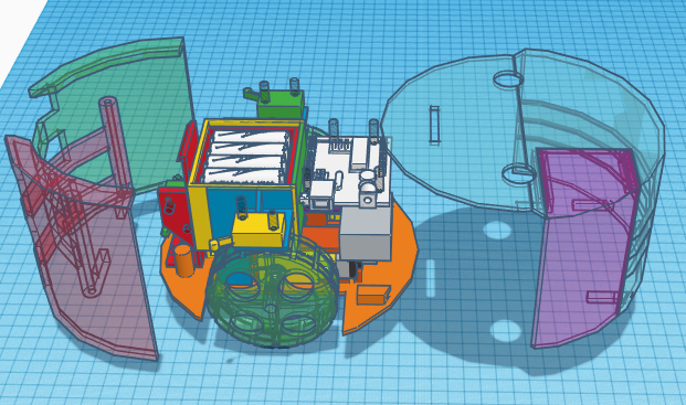
What we design:

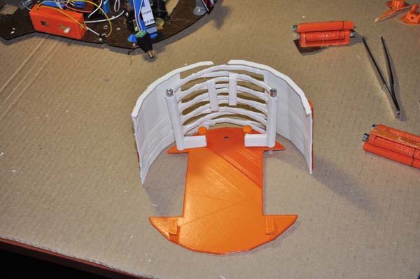
What we get:

Design
There are countless 3d designers. For this task we are going to use a simple one: Tinkercad.
This little jewel is very easy to use, does not require installation (works from your browser) and is powerful enough for any beginner level task.
Most robotic vacuum cleaners are disks. The reason is, disc can rotate in place. Anywhere, even under the stool. Angles of rectangular robot, for example, can collide with stool's legs, and rotation will be blocked. Therefore, let's design a disk-shaped robot, 180x180 mm:

Note: we do not care for the height of our robot; it isn't going to perform the actual cleaning, so it doesn't have to fit under the bed. When designing a real VC, height is very important, and the flatter means the better.
Wheels vs Tracks
The next question we have to ask ourselves is the "propulsion system". We know that the robot should rely on its circular shape by rotating around its center: this guarantees that it will not get stuck. So wheels should be positioned symmetric, regarding the center of a device. Still, we have few choices:
First:

Second:

Or even third:

Here the first solution will require an additional small wheel either in front, or in the back, to keep disk balanced (horizontal). The second and third solutions do not require such support. However, they will not work for "real" vacuum cleaner, here is why:

Here, a purple cone symbolizes a VC's side brush: as you can see, wheels will block it. Same logic, just in a less degree (why?) applies to tracks, while the first option (pair of wheels) works with side brushes just fine. The reason is, if we use two wheels, they touch the ground in a single point, far from the side brush.
As an additional consideration against tracks and in favor of wheels, note that even a vell crafted track consumes more energy. And as an additional agrument in favor of two wheels instead of four: we will only need two motors. While if we use four wheels, it is either four motors of some kind of belt or gears, so that one motor can spin two wheels. And no, we can not use "front wheel drive / rear wheel drive" approach here, remember: our robot need to be able to spin around its center, which means, wheels should work together, in sinchronized way.
Bumper
Not all robotic vacuum cleaners use bumpers. Some of them rely completely on ultrasound or infra red proximity detectors. Well... Ultrasound can be absorbed by a curtains of a plush toy, infra red can be absorbed by black object or reflected by the mirror. in both cases the robot will crush in the wall. There are few ways of dealing with it. When robot tries to run through the wall, electric current to motors increases. We can detect it, and conclude there is an obstacle. Unfortunately, when moving on a thick carpet, robot also encounters more resistance, the logic above can decide there is a wall. While when hitting the wall being on a polished wooden floor, robot's wheels can keep spinning, slipping, so the system detects no wall.
Another way of dealing with the problem is by using internal inertial sensors: when robot stops, we can detect it, no mater what surface it is on. Yet, it is not nice when the robot hits the wall on the full speed.
A reasonable compromice (one we are not going to use in our "toy" project) is to use ultrasound or infra red sensors to detect an obstacle - if we can - and to reduce speed. It works four times out of five, and robot slows down, before actually touching the wall, which looks much nicer than bumping on it.
Anyway, we are going to use bumper, even though on a tiny model like ours using remote or internal (as oppose to touch) sensors is way easier.
What is a bumper and how does it work? Well, first of all, bumper is nothing but three buttons: front one, responcible for frontal collision, left and right ones, for side collisions:
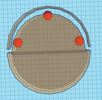
Note that bumper and a back half of a robot form a circle, so that - yes, it can spin in place, surrounded by obstacles. Now, all we need is a design that allows to have a plastic cemicircle, so that it can be pressed from front, left and right. Oh, one more thing: when pressed near top or bottom part, it should not tilt - it should go BACK:
Correct:

Wrong:

Indeed, let's say we have installed out touch sensor (a button) right behind the bumper, at 1/2 of its height. Then, if the lower part of a bumper hits an obstacle. Then the "wrong" bumper will tilt, rotating around its middle part, and the button will not be pressed! In other words, we need the bumper to move forward and back, while remaining vertical (perpendicular to the floor).
There are few solutions to this problem, the mots popular is the following:

As you can see, the bumper is connected to the vertical axes (3 of them) via joint that can only beng in a horizontal plane, while being rigid in vertical. This design will need additional stoppers to prevent bumper from going too far forward, but it is nearly optimal and used quite often... Let's not use it.
Let's invent an alternative design instead.
What we know: we can use rigid vertical axe, so that our bumper can rotate around it. However, if we attach bumper to the axe without joints, then the closer to the axe, the smaller will be the leverage, so if our VC bumps to the obstacle at the point of a bumper that is close to the axe, it might not be able to generate enough force to push the button:

Now, wouldn't it be nice if we could use the far (from the axe) part of the bumper above, while another (symmetric) bumper handles the "weak" part of our design? Unfortunately, for this to work, those to halves of our bumper should be able to move through each other:

This is a very impotrant rule you should remember: something symmetric in 2d might be asymmetric in 3d! A lot of brilliant engineering solutions is based on this little euristic. Now, let's make two halves of our bumper to move through each other:


Now we have a rigid (vertically) bumper, with few (just two, no joints, unlike in previous design) moving parts, and capable of producing sufficient (to press a button) force, when pushed from any direction.
What is wrong with this thing?!
As I have mentioned, this tutorial is mostly about inventing the bumper, because it is nearly impossible to find the schematics of that part of a VC in the internet.
So the bumper works just fine, while there are some problems that are not related to a bumper. I am going to fix them in a Floor Washer, but let's outline them here.
First, here is the video.
- The robot weight is insufficient.
- The robot moves too fast.
These two items are closely related. If you watch the video, it becomes quite obvious. The robot moves FAST. At that speed, when it hits the wall, it rotates unpredictably, so whatever algoritm you have to turn it at a specific angle... it doesn't work.
- The robot is unable to move at a straight line.
Surprisingly, it is related to first two problems, at least to some extend. Wheels slide on the dusty floor, so it moves in large circles. Also, we can not guarantee that wheels spin at the same speed.
This last problem can be fixed in one of two ways. First, we can adjust the speed of motors by adjusting voltage we feed to them. Second, we can measure that speed. Here is how: we attach a beam interruptor to the wheel, and make Arduino measure frequency of interruptions. Sounds exotic, but most likely your factory-built VC uses this approach.

So why don't we do it? Two reasons. First, as I mentioned, this tutorial is about inventing a bumper. Second - if the weight os a robot is small and speed is large, wheels will slide on the floor, so measuring the speed will be useless.
Floor Washer, another project you can find on this site, is heavy and slow, its wheels are modified for more adhesion with the floor, so it moves straight even without using beam interruptors.
Good luck :)