Algorithm for adding a road
Drawing a road in 2d space is trivial: all we need to do is using OpenCV's line function for road segments; as this function draws semi-circles at the end of the circles, we don't even have to worry about connecting lines together.
However, in 3d space we have to draw road using triangular meshes, and it is a trully formidable challenge. The road should bend as the landscape under it bends, while remaining "horizontal across its direction" as discussed above, which means we have to also add triangles to smoothly connect this road and landscape around it.
In this section I am going to follow the steps present in a "main" function of the utility.
Loading the topo map
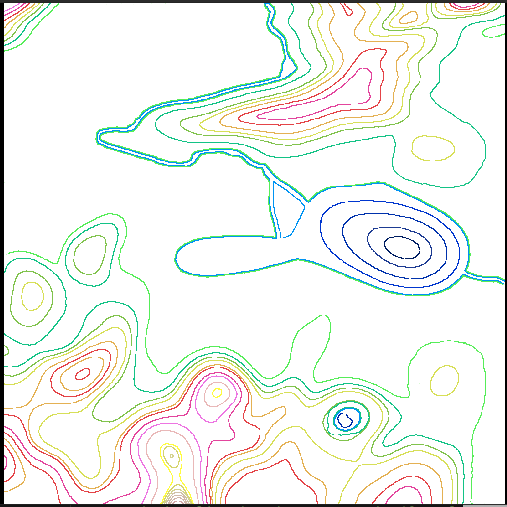
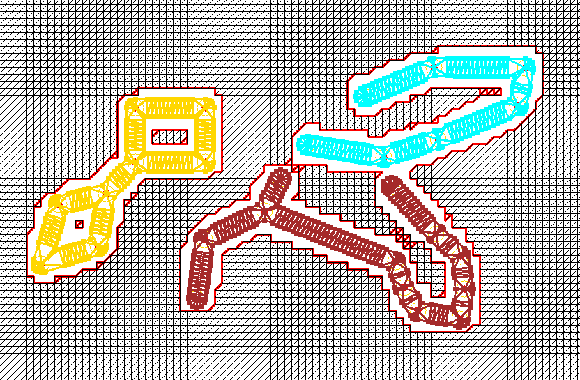
We are using three outside inputs to produce our landscape with roads. First is the topo map (see map editor section) that provides our topo-3d utility with topo lines, each using a predefined color:
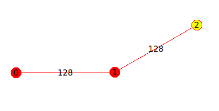
Second is a graph representing the roads network, it can be created using the Map Editor utility:

Third is a texture that we want to be pulled over our landscape - without roads on it. Roads will be added by the topo-3d utility:

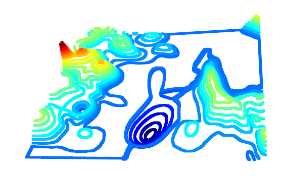
After topo map is loaded it can be converted to a (sparse) point cloud:
Building regularized point cloud
The point cloud we have at the moment is far from resembling the terrain: it is more like rings or a topo map, raised according to their color.
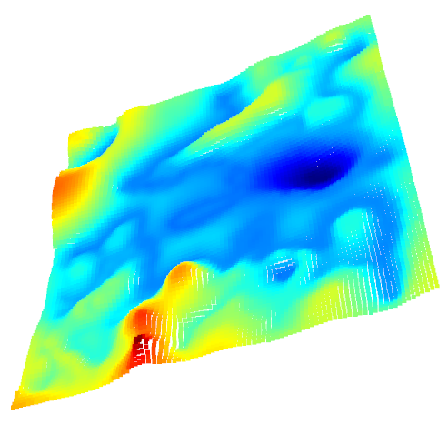
The next step is to create a "dense" point cloud, and due to convenience, I chose to make it regularized: x and y coordinates of all its points are located in a regular grid:

Smoothing the point cloud
We have a point cloud representing some kind of a surface, but it is not smooth. So some smoothing is applied to remove "steps". Here I have to mention that we do not know if any steps should be present, as topo map simply doesn't provide any info about the land between its rings. So a smoothing is applied, period.

Converting point cloud to a mesh
Technically speaking, we could have postponed this step till the very end, and the resulting code would probably run faster. However, we would also loose the chance to build our code step by step, making sure everything works as intended.
This conversion takes advantage of our mesh being regularized, which means it is very easy to switch to a cell of a "grid" to a pair of triangles, and so on for each cell of a grid the point cloud is based upon.

Loading the roads graph
Roads in our project are represented by a graph created by (see earlier sections) Map Editor utility.
The road in a Map Editor is composed of Nodes and Edges between them:
Drawing roads: Edges and Connectors
To get our roads in a form that can be converted to meshes, we are going to think of a road as of set of edges plus connectors between them. There is a difference between the Connector and a Node: the Node is just a point where two or more segments meet, while the Connector is a shape. First of all, it is flat. Think about it: two (or more) segments of a road meet in a same point, and each segment arrives there at each own angle. And remember, roads are horizontal "across the direction of a road". So as they join (and not necessarily at 180 degrees), the "connector plate" has to be horizontal in both directions.

You can see this structure in a serpantine road in the mountains: road goes up the hill, then it turns - and a spot where it turns is not tilted: it is horizontal. So we are just going to mimic what construction workers do.
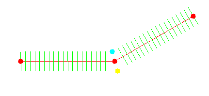
Let's start with a simple case, and add to it as we go. The road has width, and it is made of segments. Also, as it goed up and down along the landscape, we need to break each segment into some amount of sub-segments (think of a track made of segments, bending freely over the landscape). On the image below you can see such a road made of two segments. You can also see a Node (point where two segments meet) and two intersection points, left and right:

You might have noticed that there is a problem with the sub-segments of a road on the previous image: they intersect. And this is plain wrong, as we are going to use these sub-segments in future to build triangles for our mesh, we do not want them to overlap. This is where Connectors come into play. What we need is to remove sub-segments beyond certain proximity to Node:
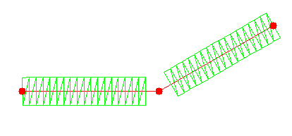
After we do that, we can break our sub-segments to triangles (remember: our ultimate goal is to turn everything into triangles and build a mesh from them):
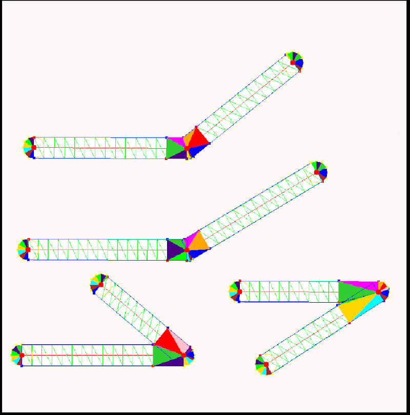
Connector therefore, is a geometry shape that fits in between all segments that meet at the same point. At the following picture you can see a lot of points used to properly draw a connector, most of these points will be removed later:

Connectors and Edges together form our road network; notice that everything in the following image is made of triangles, and therefore is mesh-ready:

Note y the way, that length of the "legs" of a connector depends of the angle roads merge at. It means that two segments of the same length may have different number of sub-segments, depending on neighbouring segments they meet with.
Turning roads into meshes
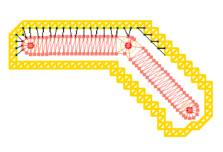
To draw triangles is not enough - we need to draw them clockwise (or counterclockwise, but consistently). It is relatively easy for edges, while for connectors I had to remove inner points and enumerate remaining (outer) points clockwise, because the way they were added was random.
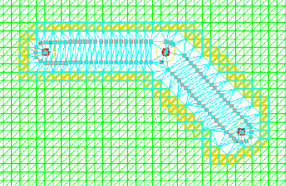
Here is a resulting 2d mesh:

To turn flat road into 2.5D one, we should set Z coordinates of the road's middle line to coordinates of corresponding points of the triangles:
The road is ready. We can of course, place our road on top of the landscape mesh, but this is not what we want. There will still be landscape triangles under it, plus, there will be a "step" between flat horizontal road and non-flat landscape:
Cleaning up space for the road
Remember, we need to remove unnecessary part of the landscape mesh (road width plus some extra space for triangles that will stitch road to landscape), same way construction workers do it in the real world:

The way we do it is by placing road on top of the landscape and removing triangles under it (plus some margin around):

Stitching
The landscape mesh is regularized, but the road mesh is not - its triangles can have any size, position and orientation. It makes stitching a non-trivial task. Unfortunately, authors of all mesh libraries I tried agree with me: none of them does a proper job.
Here is a simplified description of an algorithm (you can see details in Python code).
1. Instead of drawing a single line around the road, draw a thick line made of landscape meshes. We will work on connecting inner points of that line to outer points of a road.
2. Pick any point. Find closest one that you can connect to without intersecting any existing line (think about it: how would you approach this task?).
3. Find any existing line with the same origin:
4. Do it for all points.

5. We now have pairs of lines originating from the same points. Connect their ends:

This approach allows us to work with multiple roads by treating them as "disconnected components" (there is a large number of algorithms for that):
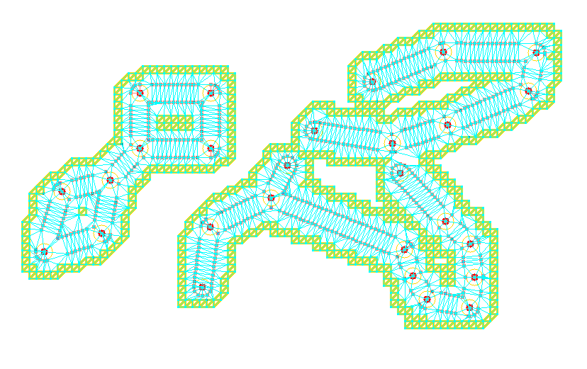
6. Now our roads are stitched to the landscape:
Converting it to a mesh
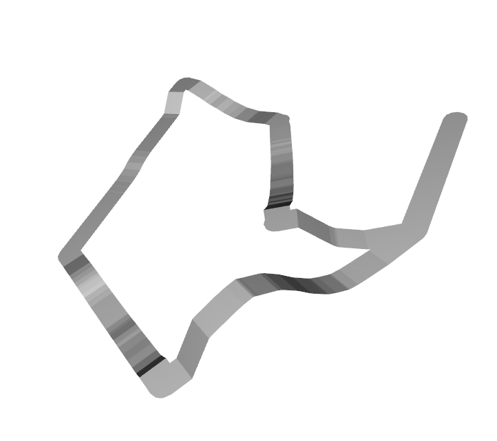
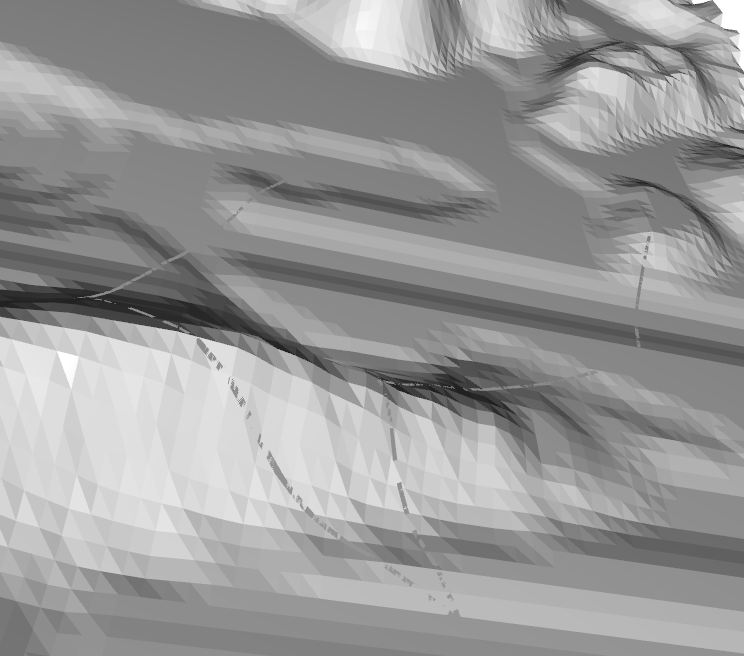
Till now I worked with multiple data structures; it is time to convert them into a mesh. I use o3d library. This is what a road looks like (no texture yet):

Let's get back to a "flat" representation and take a closer look:

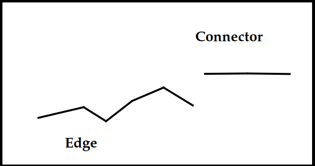
As you already know, road is made of "edges", which is a straight part, and "connectors", which are "connecting plates". You also know that connectors are horizontal, while edges are not - they follow the landscape. It means that when road meets the connector, there will be a "step":
One way of fixing this problem is by addind a fragment of the road that connects edge and connector. On the following image it is sigmoid (well, more or less), but in code it is implemented as linear:
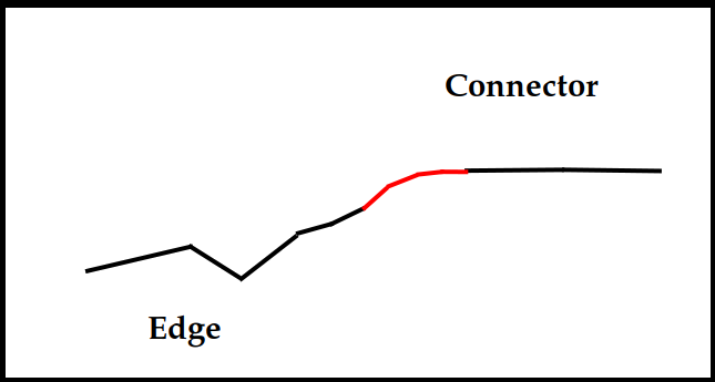
What it means: our connector now has the following parts (on each end): "main" part that follows the landscape, part connecting it to a connector, which goes up or down at a certain slope, and a non-existing part, one that would be located under connector, and was, therefore, removed.
From the practical point of view, it means that if, for example, you set length of a sub-segment to 2 meters, length of the edge is 30 meters and number of sub-segments between landscape-following part and connector is 10, it will not work: your road has 2x10*2 = 40 meters of sub-segments, while its length is just 30. Just something to keep in mind.
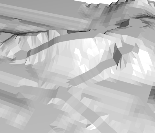
An interesting (and confusing, if you don't know what is going on) side effect of the requirement for having enough space between nodes, is the fact that if we set combination of road width, sub-segment length and extra segments between edge and connector so that the edge itself is very short (the rest is taken by linear parts), then we get less or the "road following the landscape" and more of "road cutting the mountain" look. Below, the first image presents an unrealistically wide (20-30 meters) road with other parameters set so there are almost no subgegments left for "landscape-following" part of a road:

Same roads graph, but road parameters are set to realistic 4 meters wide and proper length of sub-segments:

The problem described above will not happen very often, if will at all, because to have it, you will have to place nodes way too close. In the real world, roads do not look like that.
However, for your convenience, the utility has a bRoadsInScreenCoords flag. The name is a bit misleading, what it does is displaying everything you created on screen, so you can see if it is what you want. You can (it is done in a "main" function) set some unreasonable sizes for road width and its sub-segments, just to make your road larger on screen. This is a debug feature, of course, you will not use maps with roads 100 meters wide.
However, for this setup it is possible to get a problem above, so don't get confused if it happens. Reduce width of the road and length of sub-segments.
Adding textures
gray road on a gray landscape is almost invisible, even if you set its width unrealistically high:
As usual, I found that using 3rd party libraries is not an option, so I wrote my own code to do texture mapping. Additionally there is some (wery simple) code that adds road to a texture:


Handling brigges
If our road goes across the river, drawing asphalt on it is probably not the best idea. So now Map Editor utility supports bridges (they are displayed yellow on the graph) and you can draw roads without bridges on a mesh. The graph is still there, so navigation should work, but the texture is not affected. The idea is that you will add model of the bridge to your simulation at this spot.

