Meshes
meshes folder contains STL files that we use to create a reasonably nice looking robotic arm. "Reasonably" means that I am not going to spend too much time on it, so do not expect it to look like Optimus Prime. Note that often you will see .dae or other types of mesh files instead. It doesn't really mater, STL however is easier to 3d print if you want to build your robot. Then again, you will probably have separate STL for Gazebo and 3d printer...
In "real life", you need to make sure your meshes look like the real robot you have. Or, if you work with a simulation (say, reinforcement learning one) and want your model to run as fast as possible, you can use basic URDF cubes and cylinders instead. In the model below, I am using a compromise solution: visual part of the robotic arm is made using meshes, while collisions are calculated using basic shapes, which makes it faster. Note that as this project doesn't rely on collision tags, values in these tags are most likely wrong. In future projects I am going to provide guidance on how to pick the right ones. It is rather simple: if, for example, your mesh has a roughly cylinder shape defined in visual tag, you can use the minimal cylinder that wraps it in a collision tag, that's all.
To create meshes, I am going to use Tinkercad, the best online STL editor I know of. Here is the base_0 model in Tinkercad.

And here is a complete model:

In URDF, meshes are displayed using links, which is the same as "3d objects". Links are connected using joints, basically, a joint tells two links at which point they are connected... And this is a problem.
Let's say you have two objects and you want to connect them using a joint. You want to make sure joint is attached to the middle (vertically) of the object and not to its base. So if object's height is 1, you need to specify joint's origin tag as 0.5. So far - so good.
Unfortunately, somehow, Tinkercad saves the object's coordinates! It means that if you move the object to 100, 200, 300 in Tinkercad's design grid and save it (just an object!), and then show it using ROS2 at 0,0,0, then Gazebo and RViz will display that object at 100,200,300!
On the following image you can see what happens if we save the object (second segment of an arm in this case) right from the place it occupies in the model. It is displayed higher, as first we set its coordinates and second, same coordinates are added from STL... again.

I do not know why and how they did it, and I am not sure if other 3d editors
have same "feature", but in Tinkercad, you need to move an object to center
of grid before saving it.
This is why I have a cross made of two bars in the image above - it is centered
and it is too big to move (size of a grid), so I can center any object by
aligning it with this cross.
Well, this is not all. Let's say you have a base_0 object, and its height is 0.014. Then the joint0's origin should be at xyz="0 0 0.114". Now, let's put second object (link_1) on top of the first one, and then create a second joint to attach the third object (link_2). Joint uses parent object's coordinates and link1 is at the same "z" level as link2 (see the image above), so if we want to have link1 and link2 at the same height (distance from the floor), we need to set joint origin (z) to 0. However, it sets not only display point, but also a rotation point! And link2 will rotate around bottom of link1, not around middle of it.
To fix this problem, we need to... center link2 in Tinkercad, and then move it
down so that vertical center of a joint is at level (height) 0. Not the bottom
of an object, but the point around which we expect rotation!
Then we save it.
As the result, we can create a joint with origin that is not at 0 (vertically), but at 0 + height of a expected rotation point. And as our link_2 object was saved when positioned same distance below the ground, it will align perfectly.
I am pretty sure there is some better way of aligning two meshes before connecting them with a joint; this is just a quick review of a problem and one (rather ugly) way of solving it. As an alternative, it is possible to use visual's x,y,z coordinates to move the object around... In any case, keep in mind that we need to compensate for object position and joint origin in the same time. Not hard, but rather time consuming.
This was just one little "lifehack", there can be more. For example, take a look at robotic arm a0912. People that made it faced the same problem, but chose a different solution. You want the object to be centered from point of view of Gazebo, but be shifted to the side visually? Let's add a tiny and generally, invisible fragment to it:
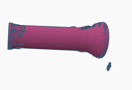
The solution, I believe, is even uglier, and it is (I believe) harder to maintain. In case you don't get it: pay attention to a little "cloud" outside of the shape itself. It is to make sure that the center of the object is calculated to be in a different position.