NRF24L01 2.4 GHz Transceiver Module
There are many ways of sending data between Arduino (or similar controller) and something else, and one of the most convenient is by using NRF24L01 transceiver module. It uses the 2.4 GHz frequency and it can operate with baud rates from 250 kbps up to 2 Mbps. The higher the baud rate, the shorter the distance, but if used in open space and with lower baud rate its range can reach up to 100 meters. Plus, there are also anthennas to increase it.

As I have mentioned, there are several variations of the NRF24L01 modules. The most popular is the one with on-board antenna. This makes the module to be more compact, but on the other hand, lowers the transmission range to a distance of about 100 meters.
The second variation, instead of on-board antenna, is using a SMA connector and a duck antenna can be connected to it to increase the transmission range.
The third variation shown here, in addition to the duck antenna, has a RFX2401C chip which includes PA (Power Amplifier) and LNA (Low-Noise Amplifier). This amplifies the NRF24L01 signal and enables even better transmission range of up to 1000 meters in open space.

The module can use 125 different channels, and it means we can create a network with 125 independently working modems. Each channel can have up to 6 addresses, or each unit can communicate with up to 6 other units at the same time.

The power consumption of this module is pretty small, it is just around 12mA during transmission, which is even lower than a single LED. The operating voltage of the module is from 1.9 to 3.6V. However, the logic pins can work with 5V signals, so we can easily connect it to an Arduino without using any logic level converters.
NRF24L01 Module Pinout

Three of these pins are for the SPI communication. They need to be connected to the SPI pins of the Arduino. The pins CSN and CE can be connected to any digital pin of the Arduino board; they are used for switching the module between standby and active mode, as well as for switching between transmit or command mode. The last pin is an interrupt pin which doesn't have to be used.
Both NRF24L01 and NRF24L01+ PA/LNA have the same pinouts.
Scrematics
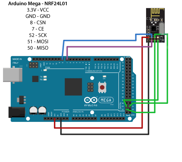
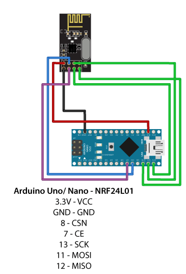
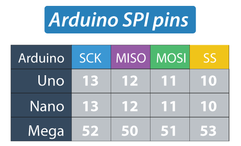
As each Arduino board has different SPI pins, we need to keep that in mind when connecting the modules to a particular Arduino board. For example:
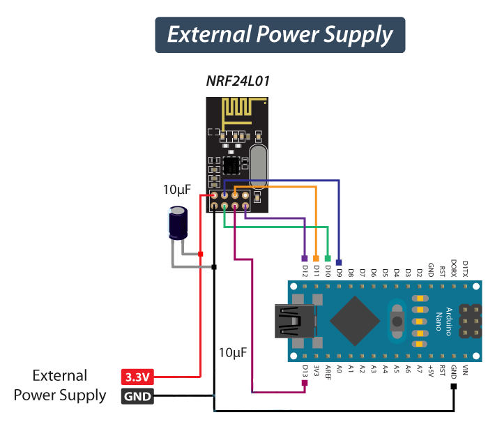
Troubleshooting
Power supply noise is one of the most common issues. It is recommended to use a decoupling capacitor across the power supply line. The capacitor can be anything from 10uF to 100uF (as shown on the schematic below).
Arduino Code
The following examples are copied from howtomechatronics.com (highly recommended.

First of all, we need to download and install the RF24 library; it will wrap and simplify some of the most tedious operations:
Code example 1:
// Transmitter Code

/*
* Arduino Wireless Communication Tutorial
*     Example 1 - Transmitter Code
*
* by Dejan Nedelkovski, www.HowToMechatronics.com
*
* Library: TMRh20/RF24, https://github.com/tmrh20/RF24/
*/

#include
#include
#include
RF24 radio(7, 8); // CE, CSN
const byte address[6] = "00001";
void setup() {
  radio.begin();
  radio.openWritingPipe(address);
  radio.setPALevel(RF24_PA_MIN);
  radio.stopListening();
}
void loop() {
  const char text[] = "Hello World";
  radio.write(&text, sizeof(text));
  delay(1000);
}

// ------------------

// Receiver Code
/*
* Arduino Wireless Communication Tutorial
*       Example 1 - Receiver Code
*
* by Dejan Nedelkovski, www.HowToMechatronics.com
*
* Library: TMRh20/RF24, https://github.com/tmrh20/RF24/
*/
#include
#include
#include
RF24 radio(7, 8); // CE, CSN
const byte address[6] = "00001";
void setup() {
  Serial.begin(9600);
  radio.begin();
  radio.openReadingPipe(0, address);
  radio.setPALevel(RF24_PA_MIN);
  radio.startListening();
}
void loop() {
  if (radio.available()) {
    char text[32] = "";
    radio.read(&text, sizeof(text));
    Serial.println(text);
  }
}
About the code:
First, we need to include the basic SPI and the newly installed RF24 libraries; then we can create an RF24 object. The two arguments we pass are the CSN and CE pins.
RF24 radio(7, 8); // CE, CSN
Then we create a byte array that represents an address, or the so called pipe through which the two modules will communicate.
const byte address[6] = "00001";
The address consists of (any) 5 characters and allows us to choose to which receiver we will talk; in our example we have the same address at both the receiver and the transmitter.
During the setup, we have initialized the "radio" object and used the radio.openWritingPipe() function to set the address of the receiver to which we will send data.
radio.openWritingPipe(address);
As for the receiver, we used the radio.setReadingPipe() function to set the same address, enabling the communication between the two modules.
radio.openReadingPipe(0, address);
Depending on the distance between receiver and transmitter, we may need different level of a signal. In our case they are located on a desk right next to each other, so a minimum signal strength is sufficient. We used the radio.setPALevel() function to set the Power Amplifier level.
radio.setPALevel(RF24_PA_MIN);
Note that if we plan on using a higher signal level, then it is recommended to use a bypass capacitors across GND and 3.3V of the modules so that they have more stable voltage while operating.
Next we used the radio.stopListening() function which sets module as transmitter, and on the other side, we used the radio.startListening() function which sets the module as receiver.
// at the Transmitter
radio.stopListening();
// at the Receiver
radio.startListening();
In the loop section of an Arduino code, for the transmitter, we have created an array of characters and filled it with the "Hello World". Using the radio.write() function we sent that message to the receiver. The first argument here is the variable that we want to be sent.
void loop() {
 const char text[] = "Hello World";
 radio.write(&text, sizeof(text));
 delay(1000);
}
As for the receiver, in the loop section we used the radio.available() function to check whether there is data to be received. If the data is available, we copy it in an array called "text".
void loop() {
  if (radio.available()) {
    char text[32] = "";
    radio.read(&text, sizeof(text));
    Serial.println(text);
  }
}
Using the radion.read() function we read and store the data into the "text" variable. As we send messages to the Arduino IDE's Serial Monitor, we can observe the results of our message exchange in the Monitor window.
Code example 2:
A second example illustrates a bi-directional wireless communication between two Arduino boards.


//Transmitter Code

/*
* Arduino Wireless Communication Tutorial
*     Example 2 - Transmitter Code
*
* by Dejan Nedelkovski, www.HowToMechatronics.com
*
* Library: TMRh20/RF24, https://github.com/tmrh20/RF24/
*/
#include
#include
#include
#define led 12
RF24 radio(7, 8); // CE, CSN
const byte addresses[][6] = {"00001", "00002"};
boolean buttonState = 0;
void setup() {
  pinMode(12, OUTPUT);
  radio.begin();
  radio.openWritingPipe(addresses[1]); // 00002
  radio.openReadingPipe(1, addresses[0]); // 00001
  radio.setPALevel(RF24_PA_MIN);
}
void loop() {
  delay(5);
  radio.stopListening();
  int potValue = analogRead(A0);
  int angleValue = map(potValue, 0, 1023, 0, 180);
  radio.write(&angleValue, sizeof(angleValue));
  delay(5);
  radio.startListening();
  while (!radio.available());
  radio.read(&buttonState, sizeof(buttonState));
  if (buttonState == HIGH) {
    digitalWrite(led, HIGH);
  }
  else {
    digitalWrite(led, LOW);
  }
}

// ------------------

//Receiver Code

/*
* Arduino Wireless Communication Tutorial
*     Example 2 - Receiver Code
*
* by Dejan Nedelkovski, www.HowToMechatronics.com
*
* Library: TMRh20/RF24, https://github.com/tmrh20/RF24/
*/
#include
#include
#include
#include
#define button 4
RF24 radio(7, 8); // CE, CSN
const byte addresses[][6] = {"00001", "00002"};
Servo myServo;
boolean buttonState = 0;
void setup() {
  pinMode(button, INPUT);
  myServo.attach(5);
  radio.begin();
  radio.openWritingPipe(addresses[0]); // 00001
  radio.openReadingPipe(1, addresses[1]); // 00002
  radio.setPALevel(RF24_PA_MIN);
}
void loop() {
  delay(5);
  radio.startListening();
  if ( radio.available()) {
    while (radio.available()) {
      int angleV = 0;
      radio.read(&angleV, sizeof(angleV));
      myServo.write(angleV);
    }
    delay(5);
    radio.stopListening();
    buttonState = digitalRead(button);
    radio.write(&buttonState, sizeof(buttonState));
  }
}
An important difference between this example and a previous one is that we are creating two pipes or addresses for the bi-directional communication.
const byte addresses[][6] = {"00001", "00002"};
We need to initialize both pipes in a setup section; here the "writing" address of the first Arduino is the same as the "reading" address of the second Arduino, and vice versa.
// at the Transmitter
radio.openWritingPipe(addresses[1]); // 00001
radio.openReadingPipe(1, addresses[0]); // 00002
// at the Receiver
radio.openWritingPipe(addresses[0]); // 00002
radio.openReadingPipe(1, addresses[1]); // 00001
In the loop section we used the radio.stopListening() function to set the first Arduino as transmitter, read and map the value of Joystick from 0 to 180, and the radio.write() function to send the data to the receiver.
radio.stopListening();
int potValue = analogRead(A0);
int angleValue = map(potValue, 0, 1023, 0, 180);
radio.write(&angleValue, sizeof(angleValue));
On a receiver side, we used the radio.startListening() function to set the second Arduino as receiver and then data availability was checked. If data are available we read it, save it to the "angleV" variable and then use that value to rotate the servo motor.
radio.startListening();
  if ( radio.available()) {
    while (radio.available()) {
      int angleV = 0;
      radio.read(&angleV, sizeof(angleV));
      myServo.write(angleV);
    }
We wait for the data to become awailable in a "while" loop. If the button is pressed the LED will light up. So these process constantly repeats and both Arduino boards are constantly sending and receiving data.