Can we use Peltier Elements for Freezing?
Peltier elements are known as a simple alternative to compression coolers and we can often see opinions that they can be used to produce deep freezers, going as far as -40C. This is... kind of true. However, there are some formidable challenges on this path making Pelier elements nearly useless for practical freezing applications.
In this article I am going to go as far as -5C, so you can get used to those challenges and ways to deal with them.
What is Peltier module
A diode array, basically. If we take plates of two different metals, say, copper and iron, and connect them together, electrons will move freely between these two conductors. Concentration of electrons at a given temperature is a property of a particular metal, so an equilibrium is established at a contact area between the two.
Now if we increase the temperature of one metal and decrease the temperature of the other, this equilibrium will be broken, so electrons will move between metals to achieve the new eqilibrium. As moving electrons means electric current, we can attach external wires and use it.
On the image below, you can see a generator used to power radio transmitters during Second World War.

The system we just described is reversible. If we create difference of temperatures, it generates current, while if we apply voltage, metals will change their temperature.
Modern Peltier elements are based on semiconductors and are smaller than their predecessors:

The black wire traditionally is a ground (minus), and the side with text is a cold side.
Controlling Peltier elements
This chapter is of a questional value: my objective is to get lowest temperature possible, so in my final experiments I will use maximum (12 V) voltage Peltier can take. However, having an adjustable power supply might be necessary for some projects, so here it is.
Let's create something we can use in our experiments, something capable of controlling multiple Peltier elements and controlling them properly.
What do I mean by properly? See, often we can find schematics online, that use a "bump" approach: we simply turn Peltier on, wait for temperature to drop to a target value, turn it off, wait for it to increase to a certain degree, turn Peltier on... This approach is wrong, as Peltier does not tolerate turning on and off very well and after some number of cycles, it will break.
So we are going to alter voltage in a smooth way instead.

Here we use Arduino to control a mosfet, and by doing so we can provide any voltage between 0 and 12V.
As we want MULTIPLE Peltier elements controlled simultaneously, let's make corresponding alterations to this schematics, just as a mater of an exercise. It is possible to use a schematics above, by the way, to power multiple Peltier modules, all you need is a more powerful mosfet. But... what if we need to power them separately, at different voltages?
So what I did was creating a simple PSB, containing FOUR schematics from the picture above:


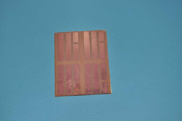
As this is an experiment, there is no need to solder elements to the PSB permanently, so I used pin connectors:


Now we can connect all this to Arduino's digital pins 3, 4, 5, 6 and control four Peltier modules independently. Peltier elements are powered from computer power block.
Please keep in mind that this is NOT a pet project powered from a battery. Currents are high enough to kill you if you are not careful enough.
For the same reason, pay attention on wires you use: they should be thick enough for max. Peltier current, which is about 6A. As we have 4 peltier elements, the wires going from power block before they split should be able to handle 6*4=24A.
Arduino is powered by USB from the computer, as, let me repeat, this is the experiment to figure out what I can do, not a final design. So I decided to not complicate things with voltage down convertors to feed Arduino from the same power supply.
Arduino code
The following code controls a little monster we just created. It is copied (and then modified) from here.
//The N-Channel MOSFET is on digital pin 3, 4, 5, 6
int arrPeltierPins[] = {3, 5, 6, 9};
int NUM_OF_PELTIER_PINS = 4;

//Power level from 0 to 99%
int nPowerLevel = 99;

// A value from 0 to 255 that actually controls the MOSFET
int nPeltierLevel = map(nPowerLevel, 0, 99, 0, 255);

void setup()
{
    Serial.begin(9600);

    for(int i = 0; i < NUM_OF_PELTIER_PINS; i++)
      pinMode(arrPeltierPins[i], OUTPUT);
}

// ---

void loop()
{
    char option;

    if(Serial.available() > 0)
    {
        option = Serial.read();
        Serial.print(option);
        Serial.print("\nInput: ");

		// Type "+" or "-" on serial terminal
		// to alter voltage from your PC.
        if(option == '+')
            nPowerLevel += 10;
        else if(option == '-')
            nPowerLevel -= 10;

        if(nPowerLevel > 99)
            nPowerLevel = 99;
        else if(nPowerLevel < 0)
            nPowerLevel = 0;

        nPeltierLevel = map(nPowerLevel, 0, 99, 0, 255);

    }

    Serial.print("Power = ");
    Serial.print(nPowerLevel);
    Serial.print(" Peltier Level = ");
    Serial.println(nPeltierLevel);

    for(int i = 0; i < NUM_OF_PELTIER_PINS; i++)
      {
		//Write this new value out to the port
        analogWrite(arrPeltierPins[i], nPeltierLevel);
//        int n = analogRead(arrPeltierPins[i]);
//        Serial.print(n);
      }
    // ---
    delay(5000);
}
A first test
Connect Peltier element to one of mosfets (ignore the rest of mosfets for now.) and increase the voltage to 99% WHILE MEASURING THE TEMPERATURE.
I personally use a cheap IR thermometer from Alibaba.
Why is it so important to measure temperature? Well, because we don't want to burn the Peltier. See, our approach (which was "just provide voltage to Peltier") wouldn't work: we need to get rid of heat somehow. And if we don't, BOTH sides of Peltier will become hot, then extra hot, and then it will die.
So be ready to interrupt this test as soon as you make sure that it is getting hot on both sides, once again, it is just an experiment.
So we need a radiator.
A (false) claim about Delta T
Here is the most unpleasant problem with Peltier elements that I found the hard way. Often, you will see claims about the difference in temperatures of the hot and cold sides is up to 60C. Maybe you can find such an element, but for those I was able to order from Alibaba, the difference is about 25C, period.
It means that to get -40C, we need to make HOT side as cold as -15, which is impossible in most
one-stage systems (*).
(*) Unless you live in Canada.
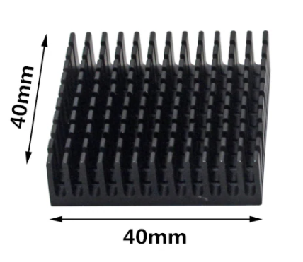
A simple radiator
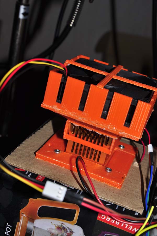
First, let's try 40x40x10 mm radiator and a 40x40mm fan.
I have 3d printed the case for it, so the hot side is cooled with fan while cold side is isolated by a cardboard and can be put inside the box we want to cool down. Well... I did that before I realized that I have to FIRST make sure it works :)

It doesn't work. The heat produced by the hot side moves through the Peltier element, and makes cold side warmer. The max difference is about 20 degrees, so the hot side becomes hoter, and even more heat moves to the cold side, and so on.
More and more radiators
In theory, what I had to do was looking for cooler's specs. If the Peltier produces 12V*6A = 72Wt, and a cooler is 50Wt, it just is not enough. Well, I learned it the hard way. And also, when you see 200Wt declared on Ali for a particular cooler, it is not necessarily true.

Again, here is a 3d printed case:
The temperature in the room was +25C, and the cold side showed a whopping 20C. Not enough.
Now, as we have the hot side temperature too high, can we lower it by providing more air?
18C


15C


13C
The next obvious approach would be using powerful coolers. The idea is to create a system that has hot side's temperature 25C higher than cold one's.

This is a (declared) 200Wt cooler with heat pipes...
10C
Do not take it wrong: if the room temperature is 20C and you use FOUR coolers like that to reduce the temperature of something size of a match box, you will get it much colder. There is a nice video on YouTube where a guy is using this approach to freeze apple juce... size of the above mentioned match box.
But in our setting the power of a cooler is not enough, it's temperature gets to about +35C, and the cold side is, predictably, +10C.
Cascade cooling
The last thing we are going to try is using Peltier modules that are connected sequentially.

Let me explain the picture, as it may not be clear. The box is underneath is just a box, I have placed the device on it for conveniebce.
The long aluminum box is a water heat exchanger; water pipes are connected to a cooler from the previous image.
On top of the heat exchanger, I have placed four Peltier elements. Why four? Well, Peltier is not 100% efficient, so to absorb all heat produced by a single Peltier, we need about four Peltier elements.
Next thing, we need to get access to the cold sides of those four Peltier elements. We can not just place a "second level" Peltier on top, as it is not large enough to reach to all four elements below. In other words, we need a heat sink.
As you can see from the image, I have used the aluminum rechangle, 3mm thick. It is getting cold (about 15C) and the "second level" Peltier is attached to it. 15 - 25 = -10, so we can expect its cold side to become that cold, but as our system looses heat (cold, actually) to the air, we only got as low as -5.
-5C
Now, obviously, if we insulate the system, cover the cold part of a heat exchanger (except where it is attached to a "second level" Peltier), we might get lower. A bit.
However, to get MUCH lower, we need to use the 3-cascade system, which will consume a lot of energy. Unfortunately, Peltier is not for freezing.