Using images as Gazebo "textures"
Design considerations
A put "textures" in quotes, as, unfortunately, Gazebo does not support dynamic textures. However, it does have a "tv-screen" like plugin, that allows us to subscribe to the images and to show them - unfortunately, only on a flat surface.
As this is a plugun, using it is extremely simple, just insert the following in the URDF of an object:
... and your object will display images you publish on a specified topic.
So the question is, where should we get these images?
When our robot receives path, it can draw it on its internal canvas. And as our robot moves around, it can add, to the same canvas, its real coordinates. Here is the problem: if we want to show "real and accurate" position, nothing prevents us from using the ground truth coordinates. But if we want to show what robot believes is true, we can use AMCL or filtered odometry. It is up to us.
Now, we can either insert the libgazebo_ros_video plugin into the world's ground plane (which is not always a good idea: what if there is something covering it?) or we can add our own "ground" object. Can we get images from a robot and just show them on such a surface? No.
Because there are, or at least can be, other sources of images. First of all, there can be more than one robot. Then, there can be a map, geographically accurate, or just texture of some grass, flowers and trails... We want to show it, too.
Therefore, we need some kind of a ImageLayersManager to get these images
from different sources, in proper order (mab at the bottom) and combine it.
So let's create a manager class, that subscribes on image topics we specified,
and publishes a single output topic, while the video plugin subscribes to it.
ImgLayersManager.py
This class does exactly what I explained above: subscribes to multiple image topics and publishes a single image topic.
PathFollower.py
Remember I mentioned that some of my classes should probably be split to multiple classes? Here is an obvious candidate: it is clearly overloaded, and in future will have to be changet into few classes. Anyway, I am going to add path drawing functionality to the same class, at least for now.
Creating and using ImgLayersManager
We have two choices here. First, we can create the object of the ImgLayersManager class in multi_simulation_launch.py, and start it using ROS2 launch description approach. Second, we can start it from the script. I am going to implement the second approach, for no particular reason.
Note that Coordinator.py is just a class that - due to historical reasons - has the most complete "main" function. So ImgLayersManager is created in thei "main", while the code of "Coordinator" class was not changed. Just a reminder: "Coordinator" coordinated path planner and path follower, nothing else.
Dynamic background texture in Gazebo
This subsection has nothing to do with path visualization, however, the idea is too obvious to be ignored. What if we add a 0th background image - will it replace the map? Or should I say, will it decorate the map, making the simulation look nicer?
Here is a very simple code that does just that. Two moments to keep in mind.
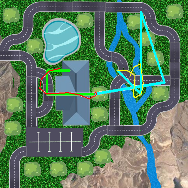
First. I used the first image I was able to draw. Paths are not
aligned with roads on the image, so do not be surprised when the robot
runs through a building. If I decide to use this approach, I will fix this behavior
later.
Second. As I already mentioned, there are many ways to organize the code.
What if the map is huge or multi layer - should we use overlapping
submaps? What if we want a vector map? What if we want different levels of
detalization depending on the scale? What should we do, if there are two
robots in our simulation, one in the building and one outside? Are those
two different maps and how to display them?
Developers often need to build the outdoor tent, but - with all those
questions in mind - they put down a foundation for a full scale skyscrapper.
Let's not make this mistake. I keep my code as simple as possible.
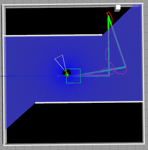
As before, image is covered by LIDAR visualization, but as we saved it for debug purposes, we can see it after the program finishes. Or we can make LIDARS less visible. Or we can use a separate display that is not located on the floor...
And just to remind you again: paths are not aligned with image, so robots move across objects they are not supposed to... It is ok.

Final thoughts
First of all, drawing on the floor is not always convenient. Here is a simple example: LIDAR visualization makes our work almost invisible:
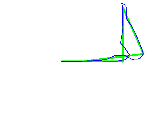
Luckily, we have the image saved independently:
And it is even worse for two LIDARs working simultaneously:
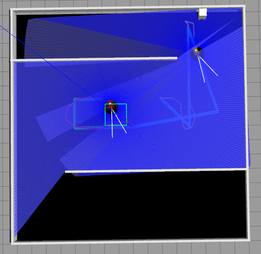

A solution might be to make LIDAR beams more transparent or to place the "screen" above the world and at 90 degrees, kind of like they do on football field, when a large screen is mounted at the side, not underneath. This approach will not work if we want to use our class as a dynamic texture, of course, but LIDARs are... well, it is not our fault.
Also, we can not "project" our "textures" to the rugged terrain, which is a major inconvenience... I am working on it.