Home
Tutorials
Transformations
Before we move any further, we need to make sure we understand what are frames our robot uses and most important, how are they are connected to each other. Particularly, WHO is responsible for this connection.


There are two possible ways frames can be related to each other: static and dynamic relations.
Statically related frames are "shifted" relative to each other, but they do not move relative to each other. A good example is a lidar that is attached to the top of our robot using fixed joint. It is not located in the center of a robot, but its relation to a center of a robot is static: it doesn't change.
Static transformations are usually described as:
$ static_transform_publisher x y z yaw pitch roll frame_id child_frame_id period_in_ms
Here, x/y/z are for offset in meters, yaw/pitch/roll are in radians (yaw corresponds to the rotation about Z, pitch is rotation about Y, and roll is rotation about X). The period is in milliseconds, it specifies how frequently a transform should be sent.
Dynamic transformations are usually implemented by publishing corresponding ROS2 topics.
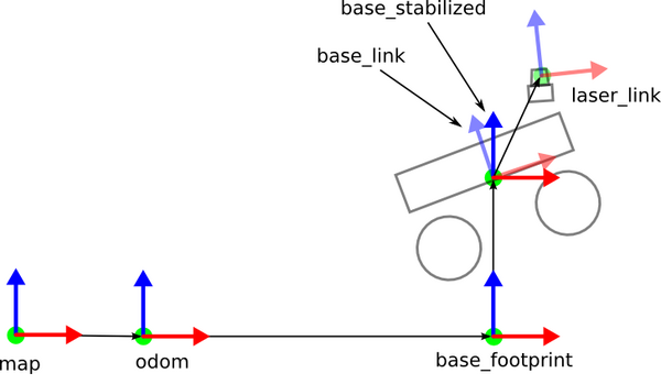
The problem with URDF is, that it is very easy to put, say, base_link to where
the base_footprint shouls be. Also, there are many places this sort of errors can
happen: just search our project for "base_link" - these are places we can make a mistake.
This is something that you should always keep in mind. For example, some navigation
plugins use base_footprint, and if it is not there, the map will behave in a
jumpy and erratic way.
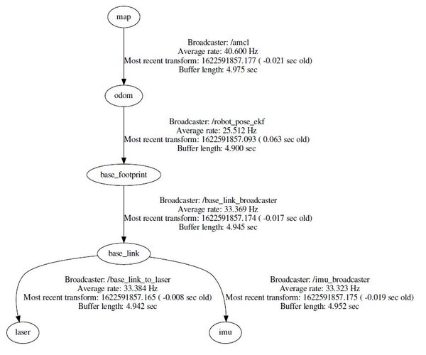
Images above present a typical hierarchy of frames of a simple robot. Let's look at that typical hierarchy closer.
Map to Odom
First (the most global one) is the map.
Let's say we want to make map and odometry frames to be equivalent. We can place the following in our launch file:
Here, the map_to_odom transformation takes the initial position of a robot (of its odom frame remated to map) as the parameter.
Note that here we assume, that odom doesn't move relative to map.
Odom to Base Footprint
This is not a static transformation, as the robot moves relative to the world. It will cause the base_footprint coordinates to change. In our example, this transformation is provided by ekf (Extended Kalman Filter, navigation) packages.
Base Footprint to Base Link
In our example, base_footprint and base_link are not moving relative to each other, but it can be different for, say, flying robot.
Note, that in our examples (below), we do not have to explicitely publish this sort of relations: some are coded in URDF (it has both base_link and base_footprint) and some are published by navigation packages, as in section above. We need to keep these relations in mind thought, in case our system complains that some relations are missing.
Base Link to Laser
The position and orientation of the laser relative to the base_link's coordinate frame. In our example, lidar is fixed on a robot's body, so relation is static.
Base Link to IMU
Same as with lidar: we have static relation betweenthese two frames: