Controlling push-pull solenoid
Introduction
Device I am going to discuss is a small variety of a larger class of devices, some can be huge... and they are not part of this article. Something like this:
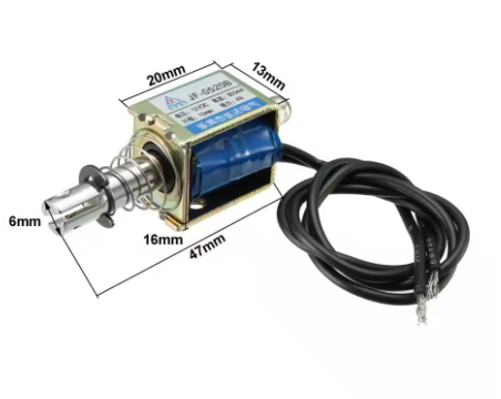
The metal rod moves as current flows through the device, which allow us to push or pull reasonably small objects.
To control this device, I am going to use Arduino, just as an example. Needless to say, other controllers can be used, like ESP32, ESP8266 and so on.
Schematics
Traditional approach uses Arduino-controlled transistor to direct power (in general case, more power than Arduino can provide) to a solenoid. As discussed in earlier section, turning such a solenoid on and off can create counteracting current, so to protect electronics from damage, diode is used. Pulling base resistor... well... pulls base of a transistor. Here is one of possible schematics. Important! Specific components should be chosen depending on parameters of your solenoid. For example, solenoid on a picture above comes in 6-12-24 volts versions. Authors of a schematic below suggested it for a 6V 300mA solenoid, I never checked their logic, but it can easily be done using logic from the previous section (relay surge protection).
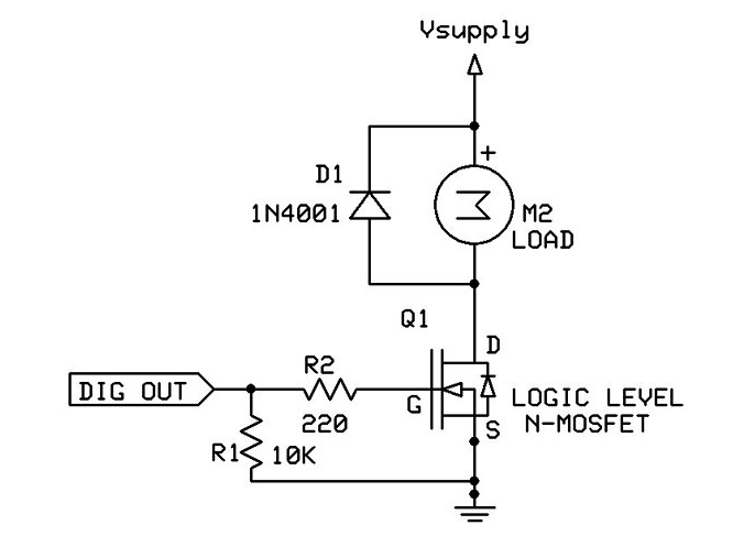
Here is another, simpler schematics. It uses 5V solenoid. The reason I am mentioning this is, solenoid can use higher voltage than Arduino can handle, in that case you will have to use a separate source of power, or maybe, a step-up/step down convertor.
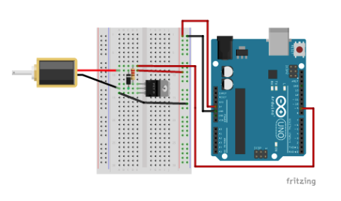
As you can see, this schematics is almost identical to a previous one, except it uses only one resistor. Also, it uses TIP120 Power Darlington Transistor. The choice of a transistor is usually based on a voltage/current it can handle.
Note:
When the transistors labeled side is facing up the legs (from left to right) are B, C, E: Base, Collector, Emitter.
The diode connects the power channel to the solenoid-ground-leg/transistor-collector-leg, preventing the damage.
The diode should be oriented with white/sliver stripe on the power channel side of the connection.
1K resistor is used to connect the Arduino pin to the Base leg of the transistor.
The Collector leg of the transistor is be connected to the ground leg of the solenoid.
The Emitter leg is connected to the ground.
Here is schematics from another source (yet, fully identical).
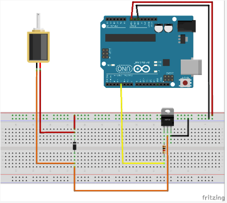
As this sort of pictures are hard to read, here is a formal schematics:
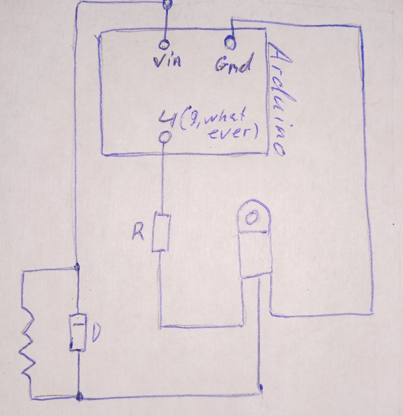
As mentioned above, solenoid can work in a wide range of voltages, depending on a model. 6-12V is a common range. Yet, Arduino uses 5V. One of possible solutions is to feed the voltage required by solenoid, to a Arduino'd barrel jack. It has voltage regulator, which will turn this high voltage to 5V Arduino requires. In the same time, it will put the original voltage (a bit less) through to a Vin pin, so we can power the solenoid from it.
More power
The Arduino's Vin pin is not designed to power high-current loads. It is possible that solenoid will require more power than Arduino can safely handle. The current for the load is drawn through the voltage regulator, which is typically rated for a maximum of 1A or less (depending on the specific Arduino model and cooling).
Same as in second schematics, this one uses TIP120 Darlington Transistor. The base resistor limits the current going to the base (control line) of the transistor; no resistor would result in no current limit, and could result in a transistor blowing up! Here, 1K ohm resistor is used; it can be placed from the base of the transistor as shown.
Suggested Solution is to use an external power supply to directly power the solenoids, bypassing the Arduino entirely for high-current loads. A MOSFET or relay can be used to control the solenoids, with the Arduino providing the control signal.
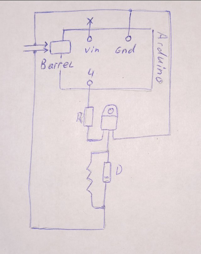
What have changed? Instead of sending "+" to barrel jack and then to Vin, and then to solenoid, we have sent "=" directly to solenoid, so high power load does not go through Arduino's voltage regulator.
As I mentioned, instead of transistors, we can use relays.
Other boards
Similar approach also works for boards that, unlike Arduino, do not provide voltage regulators. But instead of simply splitting the wires, you will have to use step up or step down converted to feed board (like ESP8266) and solenoid, each with required voltage.
Let's say we use ESP8266 board instead of Arduino.
When using an ESP8266 in a setup with 4 solenoids, you must carefully manage the power supply since the ESP8266 operates at 3.3V
and is sensitive to power fluctuations. Here's how you can set up the power distribution:
ESP8266: Requires 3.3V for operation, draws ~70-200mA during normal operation and up to 500mA during Wi-Fi transmission spikes.
Must have a stable and noise-free power supply to ensure reliable operation.
Solenoids: Operate directly at 12V and draw significant current (0.6A each, or 2.4A for 4 solenoids in parallel).
So we ended up with exactly same setup we used above in a more power section.
Code
This part is simple. We make Arduino to put voltage on a certain pin, and then transistor "amplifies" it and feeds it to a solenoid: