Spider: Electronics
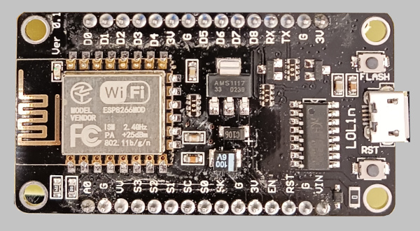
NodeMCU with ESP8266 processor
First, we need to choose a processor. As this is a simple project and simple code, Arguino-level is sufficient, we do not need to run anything advanced for spider to move around. However, Arduino itself doesn't have wireless capabilities, and adding a separate WiFi, BT or whatever else module seems too much if we can get came functionality for the same price integrated.
So, I choose to use NodeMCU - it can run same Arduino code and it has WiFi module. Now, there are many versions of this thing, for example, ESP8266 is more basic while ESP32 can, in theory, work with multi threading. Multiple threads - multiple motors, which is nice, but I am going to use ESP8266 so I can show how to implement pseudo-multithreading on a sequential processor. Plus, it is cheaper.
A particular version I use is NodeMCU v3 Lolin. It is important, as different wersions have different sizes, and I am going to design PCB for it, which simply wouldn't fit is you use something with different dimensions.
Controlling servo motors
We have 8 servo motors: 4 for horizontal legs movements and 4 for vertical ones. Now, NodeMCU simply doesn't have enough pins, so we need to use some kind of a trick to control a lot of motors with just a few pins. We use I2C. The idea is to send signals on a single line (2 pins) so that each device at the other end of the line would look for its signals and ignore signals that are intended for other devices.
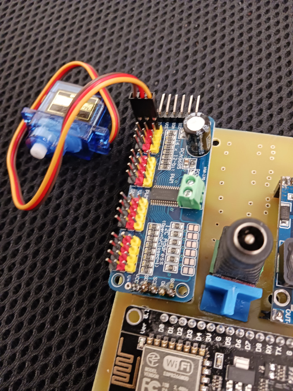
As servo motors can not do it on their own, we use an I2C aware device called PWM driver. A particular device I am going to use is PCA9685:
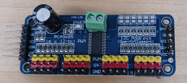
This driver takes in 2 I2C lines (SCL, SDA) and outputs corresponding signals to 16 triplets of pins. Does it mean that it can control up to 16 motors? Probably not like that, because motors take a lot of power, even small ones. And there is a limit PCA9685 can pass. Though, of course, we only need 8 motors, and if you examine the code, only 4 are used simultaneously at any moment of time. Plus, if we want, we can power motors by a separate power sourse.
.Servo motors use PWM (pulse wide modulation), which meand we send the signal to them as a pulse. The higher the frequency, the more it turns. This is handled by one of triplet of wires, as for the other two, they are power for motors. So, as I mentioned, we can use external power instead (we do not need it in this project).
Another important question: where the power comes from, if we feed motors from the driver? The NodeMCU can not provide that much power, so the PCA9685 driver has a separate input for external power. You can see it on the imag, these are contacts with screws.
Additionally, sometimes, capacitors are used to handle power spikes. I do not do it here, but it is something to keep in mind. When motor works, it creates magnetic fields, and it can induce currents. We might need capacitors to absorb those, otherwise the NodeMCU might suddenly reboot or something like that. In case of our spider, it doesn't happen.
Power source
As I mentioned above, the robot was (and still is, it is just not completed) supposed to have two major power consumers: servo motors (5-6 volts, ~200 mA each) and solenoids (12 V, 0.3A). Currently, solenoids are not used, but i am still going to plan as if they were present.
Why is this important? Because I need to deside on the input voltage of a power source. If solenoids were present, the logical choice would be to use 12V power source and to feed motors and processors using a step-down convertor, a hardware that reduces voltage. If, on the other hand, solenoids are not present, then we can use a step-up convertor to get accumulator pover (say, 3V) up to 5V required by motors.
Note that as NodeMCU can get 5V, but not 6, and servos work at 5-6V, the logical common denominator is 5V.
Note also, that power convertor, either step-up or step-down is still necessary, even if we get a 5V accumulator. As accumulator discharges, its voltage drops, which is not good; power convertor will keep it steady.
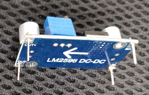
For now, I am going to use LM2596 step-down converter, assuming that the power source is 12V, later, when I address batteries, I will revisit this solution. The reason for this choice is, I promiced to show how to work with solenoids.

This convertor will take 12V from the laptop power cource and convert it to 5V for servos and processor.
Schematics
In "robotics hardware" sections of this site I already have articles on using all the components of our spider. Here I am going to put it all together. I am going to use PCB Editor (also available on this site) to create and print the PCB.
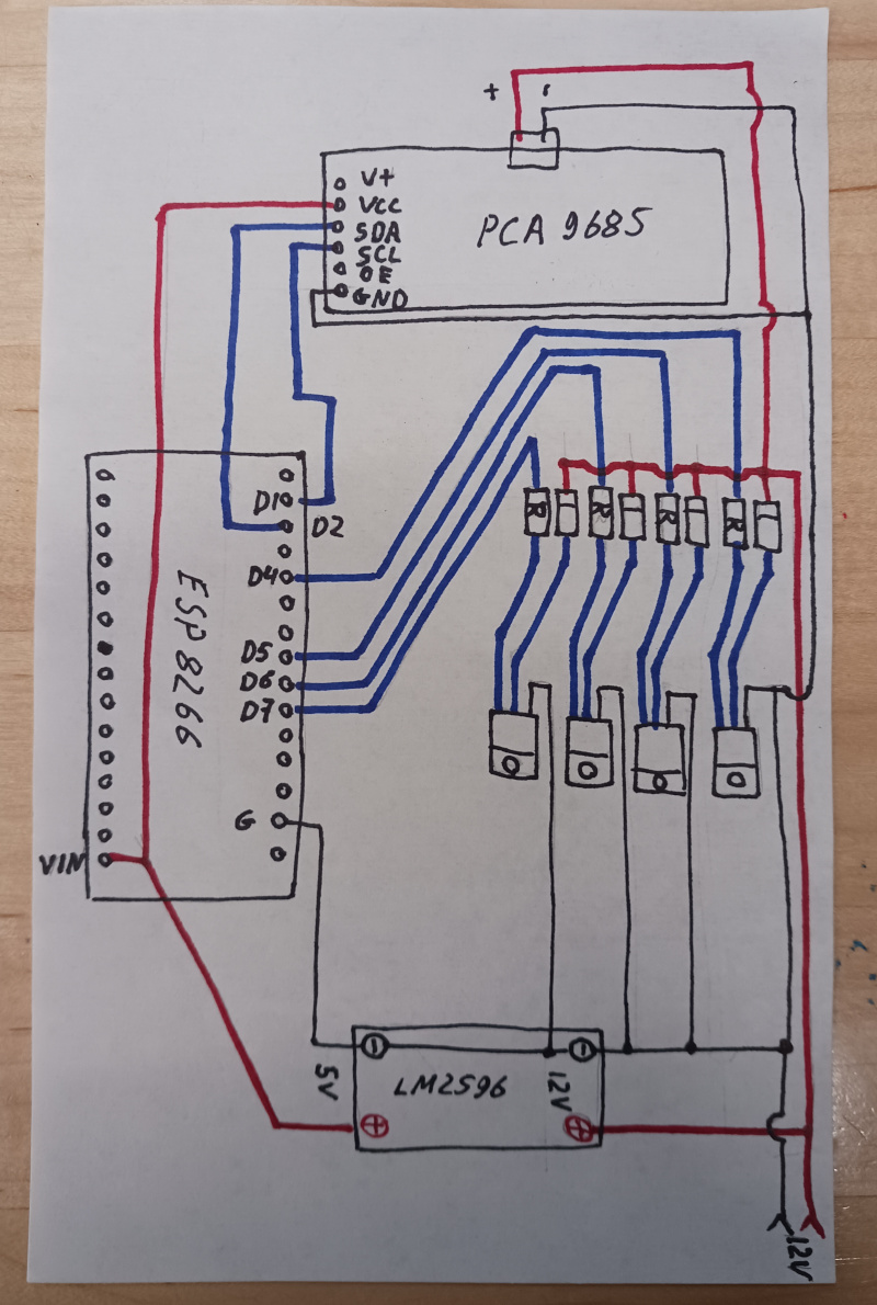
Let's walk through this schematics step by step.
First of all, if you do not want to use solenoids (I wouldn't, not in this section, but the hardware is still inplace), you can remove transistors, diodes and resistors. It will not affect servo motors.
Note that this robot is rather simple, so I have implemented it all on a single sided PCB.
Let's start with top-right corner: here we feed 12V from an external source. For this prototype, I used power source from the laptop. The important part is to add power consumption of all devices (up to 4 motors in a time plus processor, plus PWM) and to make sure the power supply can handle it.
The 12V is split: it goes to power convertor LM2596, and altso to feed transistors/diodes/resistors. As I mentioned, in this article I am not going to use solenoids, so you ban simply ignore the second part and focus on what happens after a power convertor.
Via ground ("-", black line) and "+" (red line) the power convertor feeds NodeMCU (pins G and VIN), PCA9685 (pins GND and VCC). PCA9685 also gets power to the connector located in the middle of it: this power is passed to servo motors. Technically, we can send there up to 6 volts, but I chose to use 5V everywhere.
Pins D1 and D2 of NodeMCU are connected to PCA9685 SCL and VCC: they form an I2C so 2 lines can be used to control 16 motors (motor pins of PCA9685 are not shown).
Let's also walk through the part that controls solenoids. As I explain in the "software" section below, the 4 solenoids can be used to control 4 vacuum cups so, if the algorithm of walking is changed to imitate animal's shoulder blade, the robot would be able to move on a vertical glass. I am not sure when I will finish this part, but controlling solenoids is here, anyway.
What we do is using 4 pins (D4, D5, D6, D7) to control transistor. Depending on LOW or HIGH signal on these pins, the transistor opens or closes, sending current through the solenoid, that's all. The resistor "pulls" the base, a trick you see very often in electronics, it is to make sure initial state of a base is what we want and not something random.
Solenoids (not shown) are connected to opposite sides of each diode. Diode makes sure the current runs in one direction and when off, the induced (by solenoid returning to "off" position) current doesn't run backwards, damaging electronics.
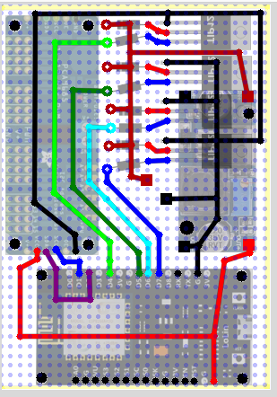
In PCB Editor, it translates to the following design:
The differences are only in the way I moved wires around so that a single layer PCB can be used.
Implementation details
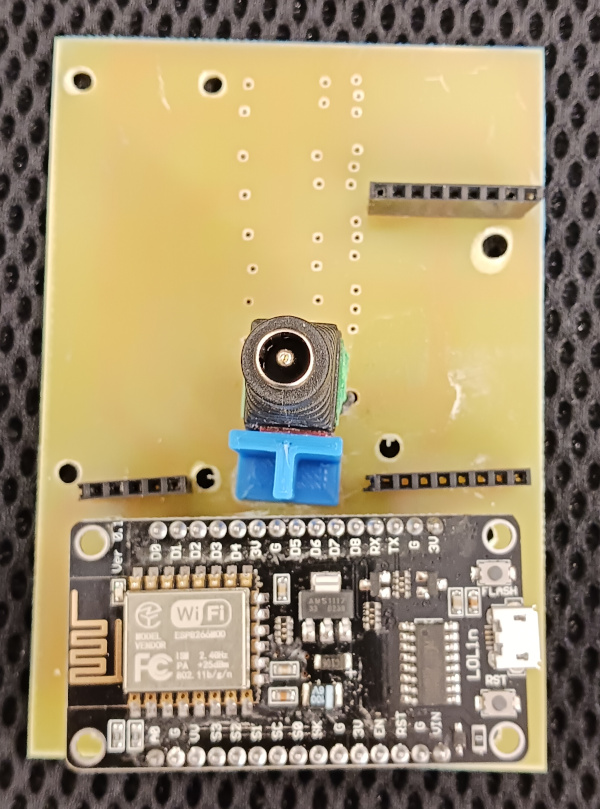
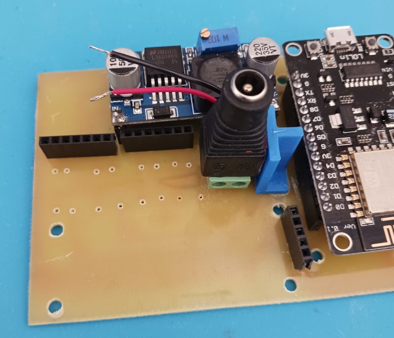
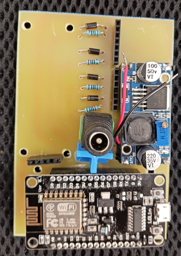
We start with PCB we got in PCB Etching section. We use thin drill to make holes where contact pins will be attached. Not all pins (of, say, NodeMCU) are used, so we can as well not drill extra holes:
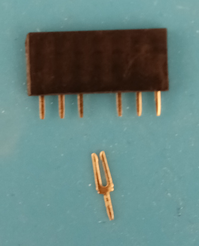
We only need contacts for NodeMCU (on the image they are hidden under NodeMCU itself), for PWM driver and for power convertor. We also use the support element to glue power barrel to PCB.
Speaking of LM2596 power convertor. It comes without pins: there are metallized holes and you can attach wire, pin or whatever else you want.
The problem with this approach is, I don't really NEED this robot, so I am going to build it, make sure it works, and take it apart. So I am going to use pins, this way the component can be installed and removed fast and easy. Another reason for this design choice is quality: one of my power convertors simply didn't work out of the box, so I have a choice: either to test components before installing them, or make the system to test them by design. Anyway, here are pins that I have soldered to it:
As for PCA9685, I have soldered pins to it, following the same logic, but as these pins are on one side only, the opposite end of a component will hang in the air, which is not good. To fix the problem, I have placed a small plastic cube under it, with double-sided sticky tape on both upper and lower sides.
Motors are attached to any triplet of pins on LM2596, as we have less motors than pins, I find it convenient to use every second triplet, this way disconnecting the motor is easier.
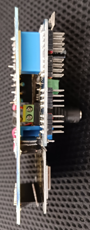
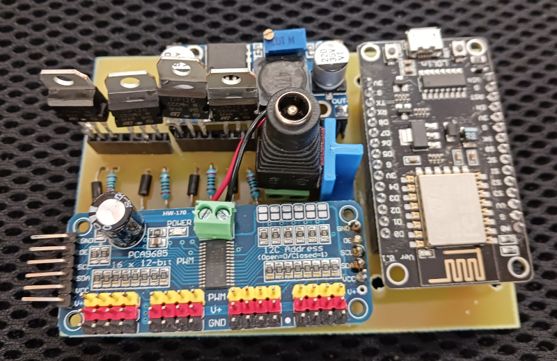
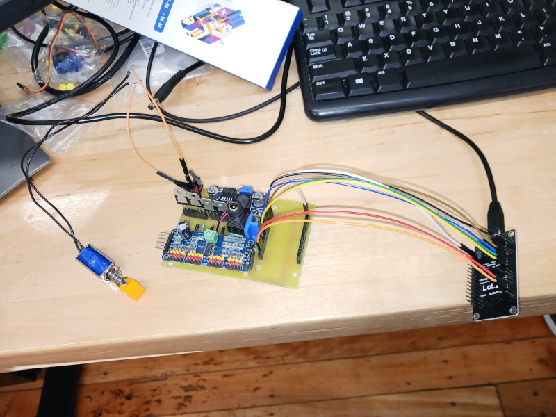
Here is the PCB with all (but solenoid related) components installed:
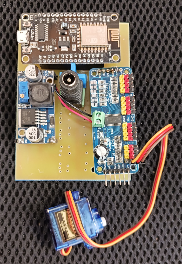
Keep in mind that it is a temporary solution, when (and if) I will be done with software part, I will replace this barrel and power convertor and add batteries, most likely, using a ready-to-use powerbank.
Note the way I used printed plastic holder to glue the power barrel to the PCB. Also note red and black wires it exposes. Those will go through the hole in PCB to the opposite side and will be soldered there to input power lines.
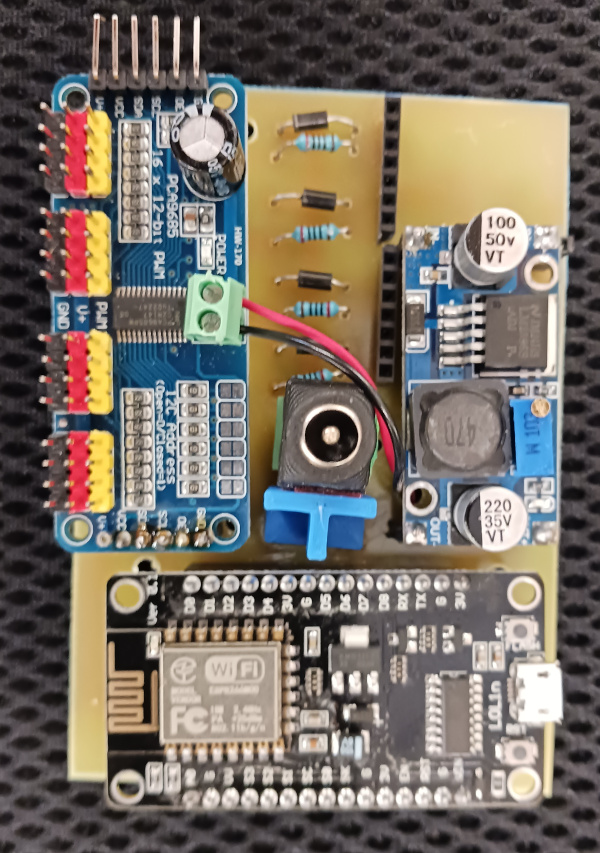
Next step, if we want solenoids, we install diodes and resistors. Note the female slots for pins (vertical on the image): those are for transistors. The logic is the same: I want to be able to salvage transistors later, plus soldering transistors is risky in general (possible, but don't overheat), plus it is possible to burn transistors while experimenting, after all, it is not a well adjusted serial production.
Here I have a problem: should I put ALL components on female pin adapters so they can easily be removed? I chose to solder diodes and resistors.
Same, but with PWM driver in place. As this component is attached using sticky cube, I install it last, so i don't have to remove it to do soldering.
Now we can insert transistors:
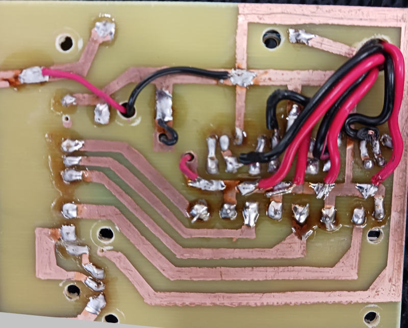
As I mentioned earlier, solenoids are attached to the opposite pins of diodes. I simply soldered the wires, and moved them to the opposite side of a PCB using a large drilled hole. for serial production, of course, there are better design solutions.
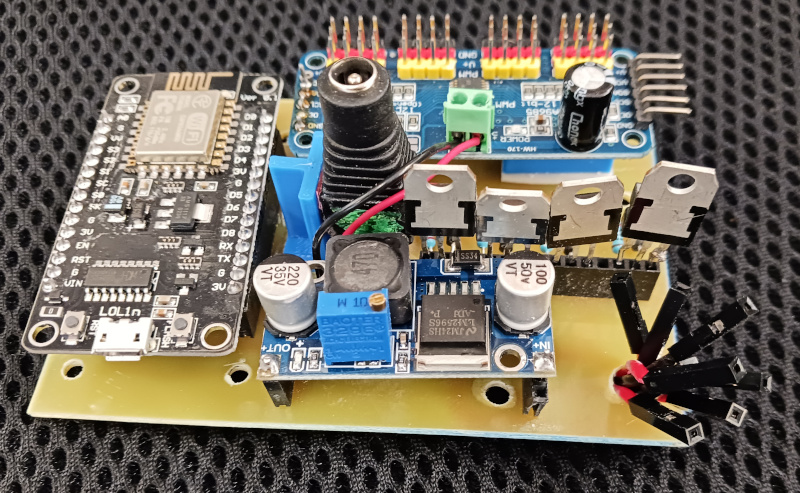
This is what it looks like, and yes, it is an ugly solution. Simple, reliable, but definitely something to redesign:
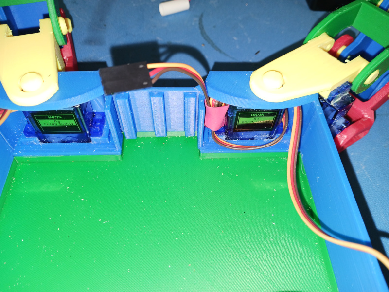
Motor wires are too long, and I had two choices: either cut them and re-solder, or use thermo-shrink tubes to keep them tidy. I chose to not do extra work:
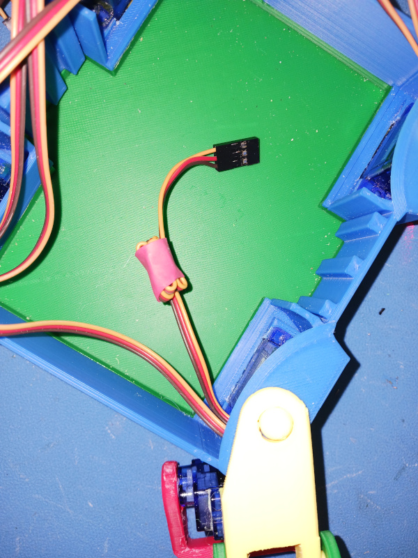
In my design, there are special "compartments" for these wires:
Regardless the fact that I do not use solenoids in this article, it is still possible to connect them and make sure the code (see the software section below) works:
Switching to batteries
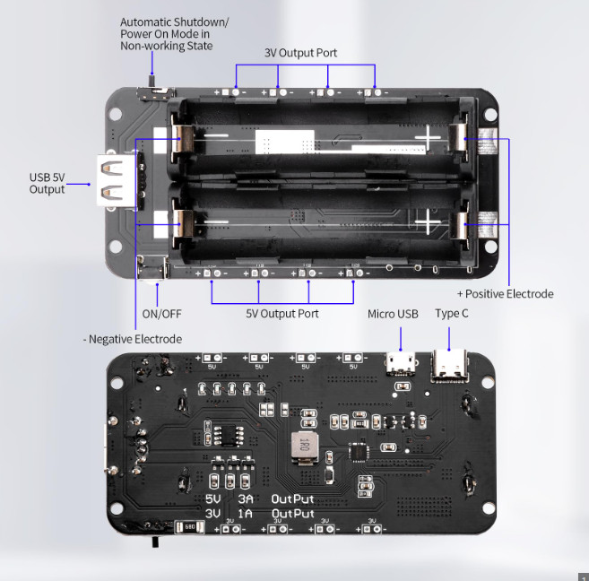
This was not part of the original plan, so the resulting design is a bit more ugly than usual. What I did was removing power convertor (remember, it uses pins, so it can easily be pulled out) and inserting wires with male pins instead. These wires went outside and were attached to a simplest powerbank I was able to find on Amazon:
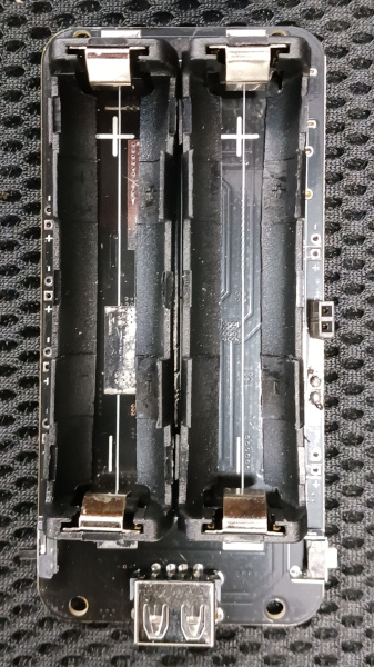
Important note: Regardless the fact that the spider robot is well designed in terms of reliability and accuracy (no jerking, no motor overloading and so on), it is a quick and dirty design nevertheless. One of the symptoms, so to speak, is the fact that I use glue where bolts and nuts were supposed to be used. Particularly, once the cover of the robot (one with Bender on it) is glued to place, you can not alter the schematics anymore. But... we just removed the power convertor! That means we are now stuck to battery power, and we DO NOT (another design flaw) have access to USB of a NodeMCU. We can not alter the software after we glued the cover to a robot!
The reason is kind of obvious: I never intended to use (and therefore, to improve) this robot, it was a pet project with the only purpose: to create this tutorial. So I have created all the software I needed while using power supply of a laptop, and only then removed the convertor and glued the cover to its permanent place. No harm done, but still... poor design.
Back to batteries.
This particular powerbank is able to output regulated 5V, which is exactly what our spider needs (note that we do not use solenoids in this article). So instead of using 5V output of convertor, we use 5V output of powerbank.
I simply glued the powerbank using 2-sided tape, which is NOT a good design solution:
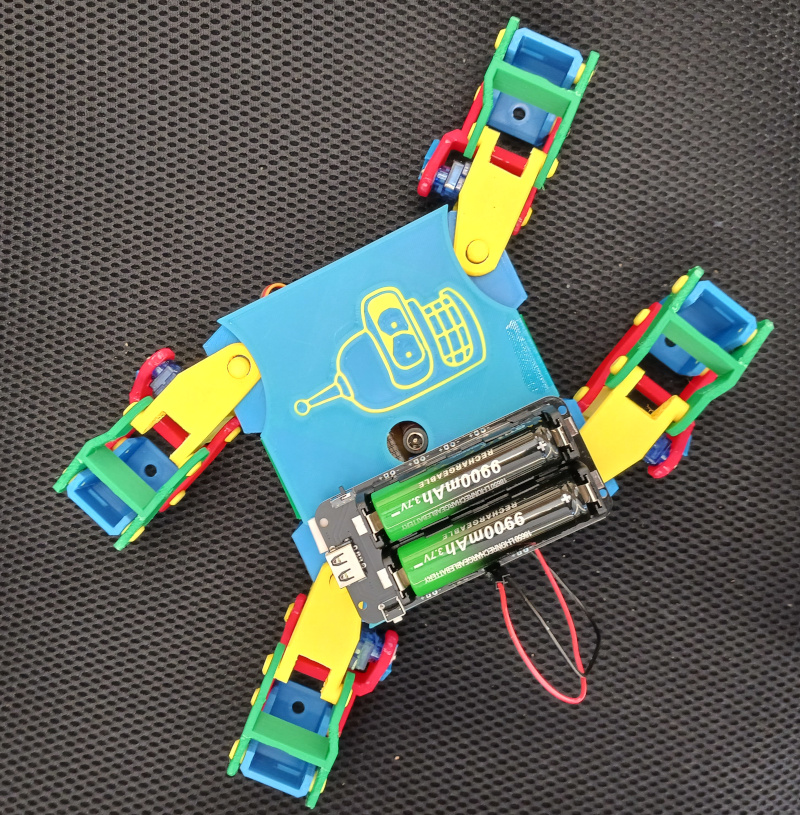
Powerbank has on/off switch, so I don't even have to install that.