Using PWM driver
Controlling servo using PWM driver
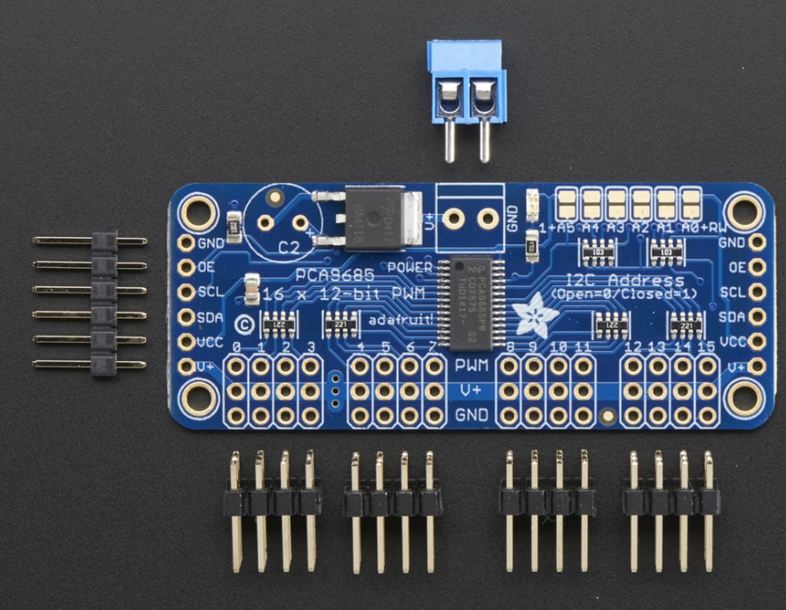
If you have too many peripherial devices, you can run out of Arduino pins. One of the possible solutions is using PWM driver. Let's use PCA9685 PWM/ Servo Driver as an example.
This is a 16-Channel 12-bit PWM and servo driver which communicates with Arduino using the I2C bus. Additionally, it has its own timer, so controlling multiple servos places less computational load on Arduino.
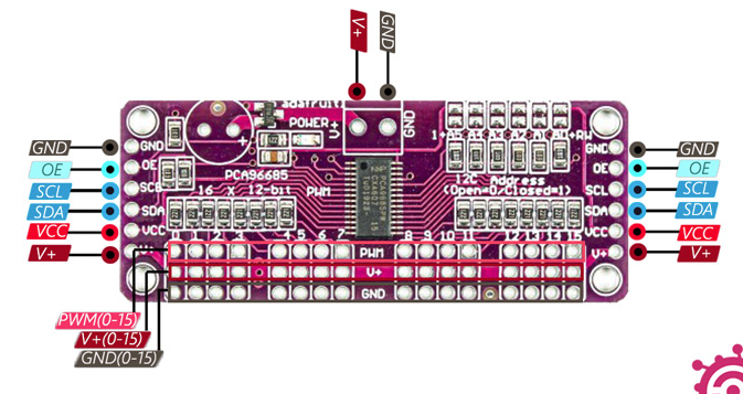
Power Pins
GND - power and signal ground pin, must be connected
VCC - logic power pin, should be 3 - 5V max! Also used for the 10K pullups on SCL/SDA so unless you have your own pullups,
have it match the microcontroller's logic level too!
V+ - optional power pin that will supply distributed power to the servos. Leave disconnected if not used.
Chip does not use it. Power can also be provided from the 2-pin terminal block at the top of the board (5-6V DC if you are using servos).
If you have to, you can go higher to 12VDC, but do not connect VCC to V+!
The VCC pin is just power for the chip itself. If you want to connect servos or LEDs that use the V+ pins, you MUST connect the V+ pin as well. The V+ pin can be as high as 6V even if VCC is 3.3V (the chip is 5V safe). We suggest connecting power through the blue terminal block since it is polarity protected.
Control Pins
SCL - I2C clock pin, connect to your microcontrollers I2C clock line. Can use 3V or 5V logic, and has a weak pullup to VCC
SDA - I2C data pin, connect to your microcontrollers I2C data line. Can use 3V or 5V logic, and has a weak pullup to VCC
OE - Output enable. Can be used to quickly disable all outputs. When this pin is low all pins are enabled.
When the pin is high the outputs are disabled. Pulled low by default so it's an optional pin!
Output Ports
There are 16 output ports. Each port has 3 pins: V+, GND and the PWM output. Each PWM runs completely independently but they must all have the same PWM frequency. That is, for LEDs you probably want 1.0 KHz but servos need 60 Hz - so you cannot use half for LEDs at 1.0 KHz and half at 60 Hz.
They're set up for servos but you can use them for LEDs! Max current per pin is 25mA.
There are 220 ohm resistors in series with all PWM Pins and the output logic is the same as VCC so keep that in mind if using LEDs.
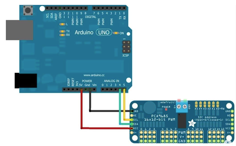
Connecting to the Arduino
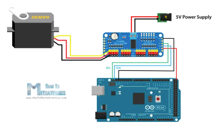
The PWM/Servo Driver uses I2C so it take only 4 wires to connect to your Arduino:
"Classic" Arduino wiring:
+5v -> VCC (this is power for the BREAKOUT only, NOT the servo power!)
GND -> GND
Analog 4 -> SDA
Analog 5 -> SCL
Older Mega wiring:
+5v -> VCC (this is power for the BREAKOUT only, NOT the servo power!)
GND -> GND
Digital 20 -> SDA
Digital 21 -> SCL
R3 and later Arduino wiring (Uno, Mega & Leonardo):
(These boards have dedicated SDA & SCL pins on the header nearest the USB connector)
+5v -> VCC (this is power for the BREAKOUT only, NOT the servo power!)
GND -> GND
SDA -> SDA
SCL -> SCL
Adding a Capacitor to the thru-hole capacitor slot
There is a spot on the PCB for soldering in an electrolytic capacitor. Based on your usage, you may or may not need a capacitor. If you are driving a lot of servos from a power supply that dips a lot when the servos move, n * 100uF where n is the number of servos is a good place to start - eg 470uF or more for 5 servos. Since its so dependent on servo current draw, the torque on each motor, and what power supply, there is no "one magic capacitor value" we can suggest which is why we don't include a capacitor in the kit.
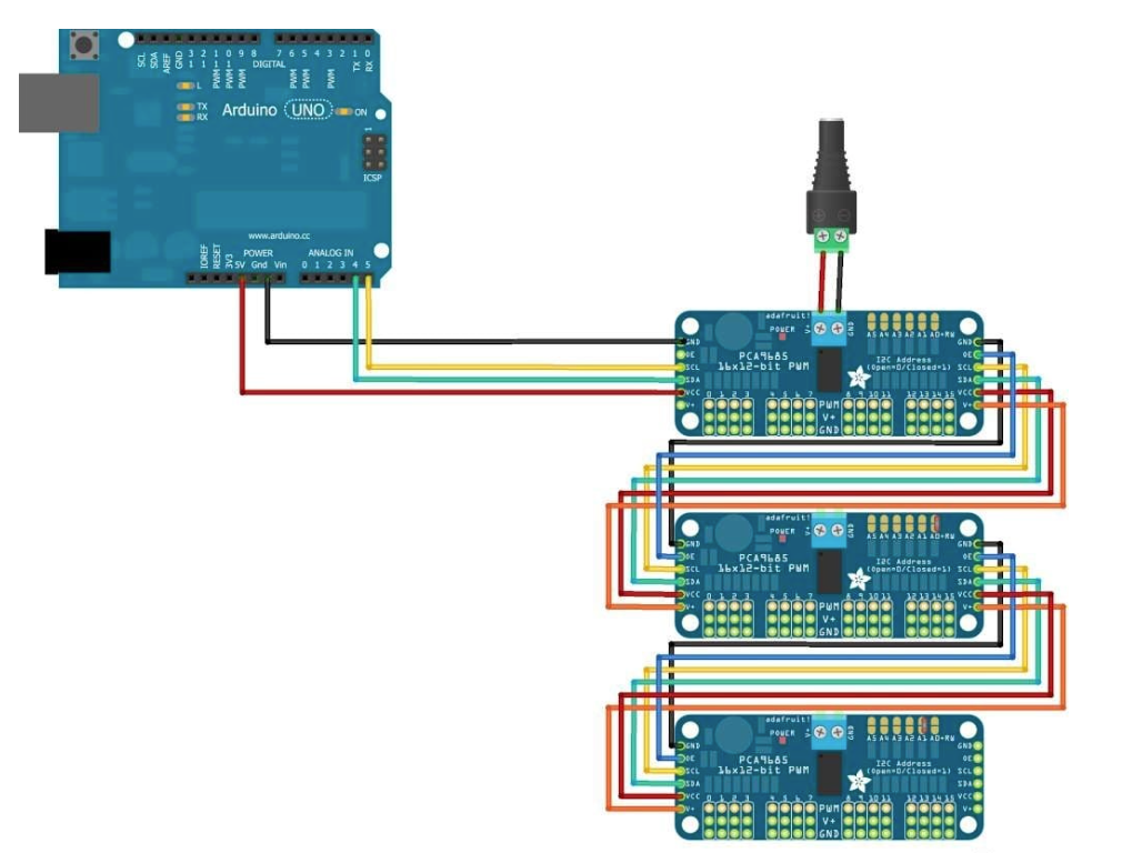
Chaining controllers
We can chain up to 62 of these drivers on a single I2C bus. So we can control up to 992 servos using only the two Arduino I2C pins. The 6 address select pins are used for setting different I2C addressed for each additional driver. We just need to connect the solder pads according to this table.
We need to assign each board with the unique address using the address jumpers on the upper right edge of the board. The I2C base address for each board is 0x40, and the binary address that you program with the address jumpers is added to the base I2C address.
To set the address offset, solder to bridge the corresponding address jumper for each binary '1' in the address.
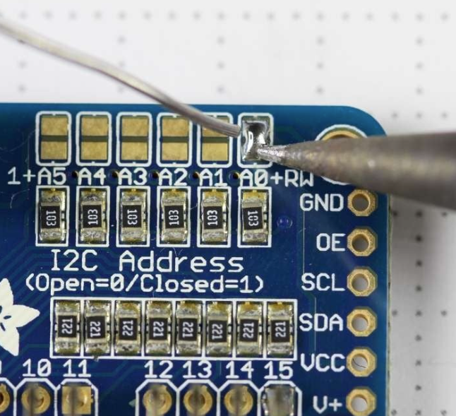
Board 0: Address = 0x40 Offset = binary 00000 (no jumpers required)
Board 1: Address = 0x41 Offset = binary 00001 (bridge A0 as in the photo above)
Board 2: Address = 0x42 Offset = binary 00010 (bridge A1)
Board 3: Address = 0x43 Offset = binary 00011 (bridge A0 & A1)
Board 4: Address = 0x44 Offset = binary 00100 (bridge A2)
To address different (chained) boards:
Here is the sample schematics:
To control it using Arduino:
We can use both Servo library or Adafruit servo library.
In Arduino environment, Go to Library manager and search for Servo and then install Adafruit PWM Servo Driver Library To begin reading sensor data, you will need to install the Adafruit_PWMServo library (code on tteir github repository). It is available from the Arduino library manager. Then run the following code:
Now let's take a look at the Arduino code, using another approach. For controlling this servo driver we will use the PCA9685 library which can be downloaded from GitHub.
We should create separate PCA9685 object for each driver, define the addresses for each driver as well as set the frequency to 50Hz. Now simply using the setChannelPWM() and pwmForAngle() functions we can set any servo at any driver to position any angle we want.