Home
Tutorials
Controlling motors with ESP8266 and L293D
Introduction
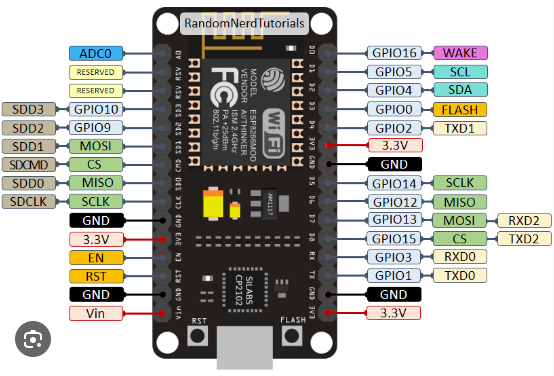
This time let's use NodeMCU ESP8266 instead of Arduino, just because ESP8266 (and especially ESP32) is better, while capable of running same code. In most cases, there is simply no reasons to choose Arduino. Personal opinion, I do not insist.
NodeMCU ESP8266:
Theory
L293D motor driver:
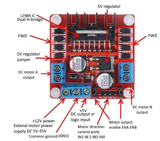
L293D is a 16 Pin Motor Driver IC. It can control two motors rotating in any direction, or one bi-polar or uni-polar stepper motor. L293D IC is a dual H-bridge motor driver IC. One H-bridge is capable to drive a DC motor in any direction. L293D IC is a current enhancing IC as the output from micro controller is not enough to drive motors.
The current limit is 600mA.
The DC motor speed is directly proportional to the supply voltage, but using it to control speed is inconvenient. Instead, we use PWM (Pulse Width Modulation). PWM is a technique where the average value of the input voltage is adjusted by sending a series of ON-OFF pulses. The average voltage is proportional to the width of the pulses known as the Duty Cycle.
VCC pin supplies power to the motor, anywhere between 5 to 35V can be applied. If the 5V-EN jumper is in place, you need to supply 2 extra volts than the motor's actual voltage requirement, to run the motor at its maximum speed.
5V pin supplies power to the switching logic circuitry inside the L298N IC. If the 5V-EN jumper is in place, this pin acts as output and can be used to power up the Arduino. If the 5V-EN jumper is removed, you need to connect it to the 5V pin on Arduino.
The speed control pins ENA and ENB are used to turn on/off the motors and control its speed. Setting these pins HIGH will cause the motors to spin, while pulling it LOW will stop them.
IN1 & IN2 pins are used to control the direction of Motor A. If IN1 is HIGH and IN2 is LOW, Motor A spins in a certain direction. To change the direction, make IN1 LOW and IN2 HIGH. If both the inputs are either HIGH or LOW, Motor A stops.
IN3 and IN4 control the spinning direction of motor B.
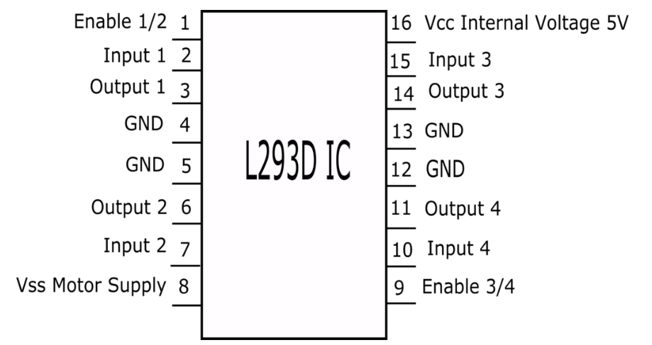
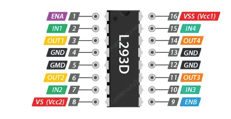
Schematics
Connecting to NodeMCU not using PWM:
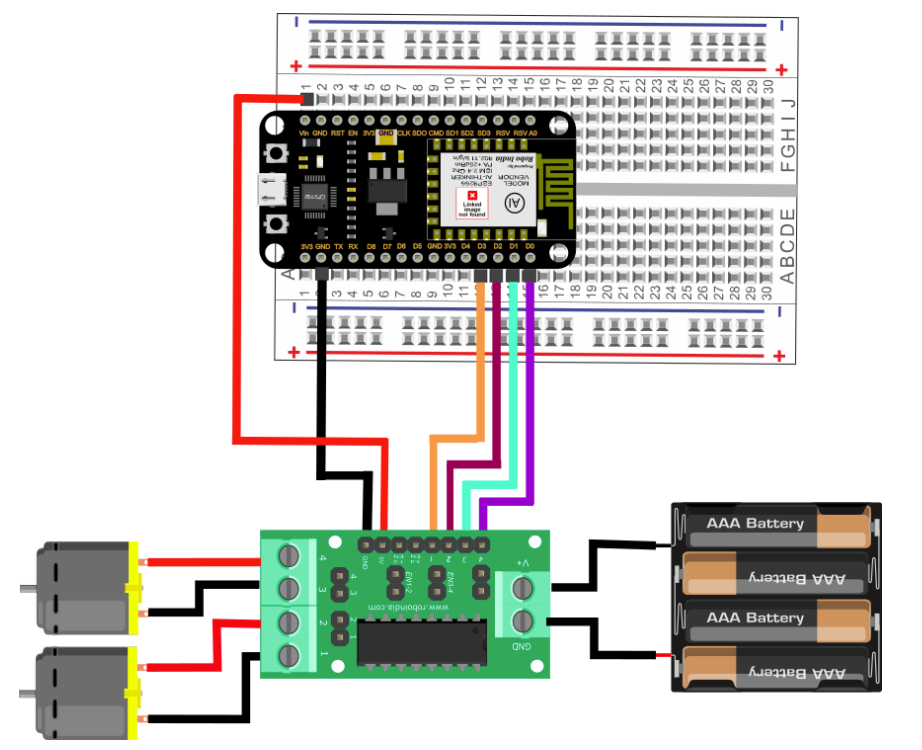
Make sure that the Jumpers are preset on the Enable 1-2 and Enable 3-4 pins of module, so that motor will be enabled and work at maximum speed.
Connection with NodeMCU using PWM
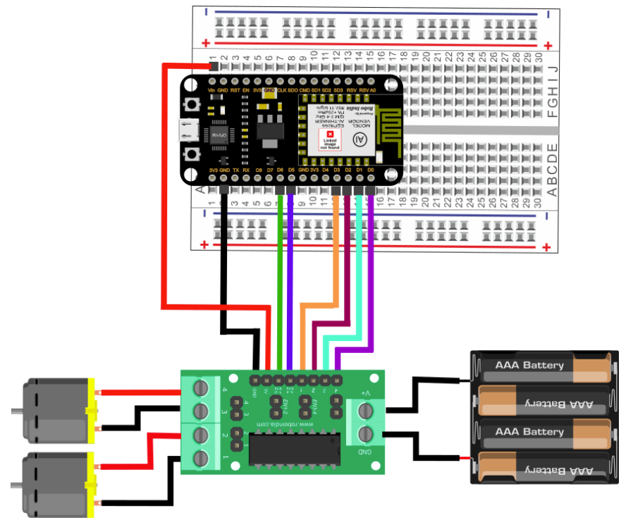
Make sure to remove the Jumper preset on Enable pins of module, so that we can connect PWM input to this pin and control the speed of motors. If we connect these pins to ground , then the motor will get disabled.
Code
Without PWM:
With PWM:
Links