Controlling servo motors with Arduino
Introduction
In this section i am going over controlling servo motors with Arduino.

Circuit
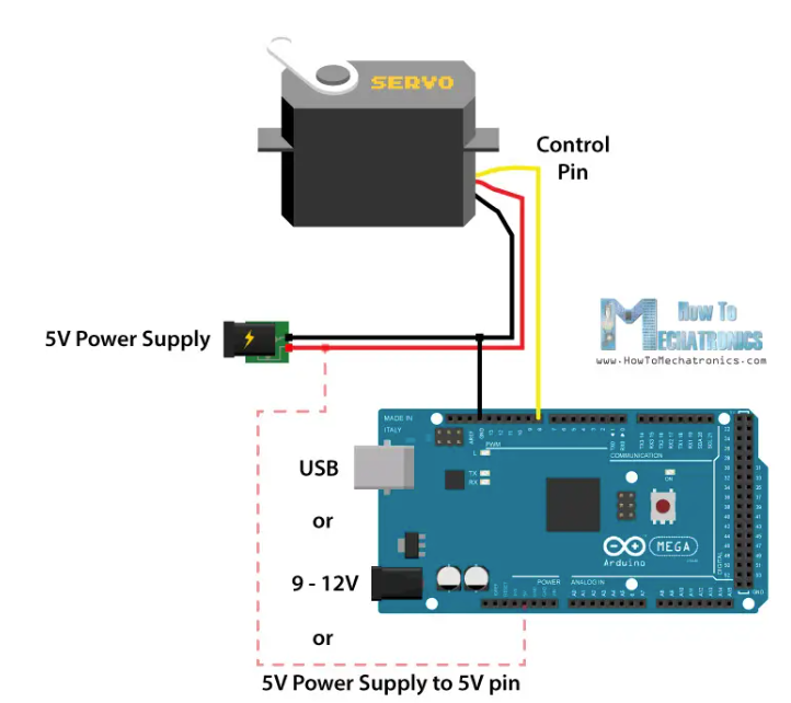
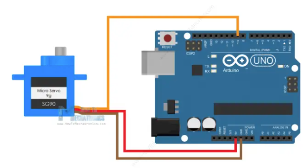
Here is a simple schematics:

We power both Arduino and servo motor from a 5V power supply. We put power directly to 5V pin (which is not necessarily a good idea, as what if power fluctuates as servo load increases). Using Arduino's barrel jack is another option.
Yellow wire is to send commands from any Arduino digital pin to servo.
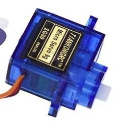
I am going to use S90 Micro Servo: it has low current consumption (around 100-200mA no-load running current, around 500-700mA stall current). On the other hand, the Arduino 5V pin can output only around 500mA if powered via USB, or up to 1A in powered via the barrel connector. So some sources suggest (for low power servos):

I would advice against it, unless you are sure you know what you are doing.
Code
Arduino can control servo via PWM. The following code sends controlling pulse to servo:
As you can see, different pulse duration corresponds to different angle of rotation of servo's shaft.
However, this approach is not convenient. Arduino has a library called Servo that does what we need in a background:
Here, instead of pulse durations, we supply rotation angles, which is much more convenient.
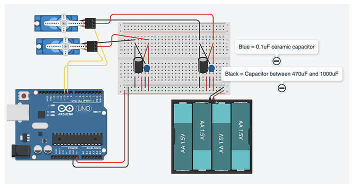
To control multiple servos, we simply create more than one Servo object:
Using capacitor to stabilize
Sometimes servo motor resets Arduino board. The reason is, it can draw significant current when at load. In order to solve this issue we can use a capacitor across the GND and the 5V pin. Electrolytic capacitors might be added to the output of the power supply if you can see instability in the voltage. But while they will limit the voltage sag, they also lengthen the time of the sag because the capacitors also need to be recharged!

Calibrating the angle
Servo motor is an analog device, and to make it move from 0 to 180 degrees you may need to perform calibration. For example, in theory, a pulse width of 1ms (0.5ms) corresponds to 0 degrees position, and 2ms (2.5ms) to 180 degrees. However, these values can vary from servo to servo and between different manufacturers.
Arduino Servo library has the attach() function that can be used to adjust the pulse widths values. The attach() function can take two additional parameters (see code above), the minimum and maximum pulse width in microseconds. The default values are 544 microseconds (0.544milliseconds) for minimum (0 degrees) angle, and 2400 microseconds (2.4ms). By adjusting these values we can fine tune the range of the servo.