Home
Tutorials
Blinker Example
Introduction
A "Blinker" program is a bare minimum to start with ESP8266. It allows you to turn a light diode on and off. Of course, to master this tutorial, you have to lear the board's pinouts, as well as installation and programming. In other words, if you this subject is new for you, do not miss this tutorial.
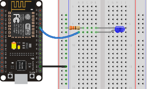
We are going to blink the on-board as well as an external diode; they are connected to the same output pin, so they'll blink together.
Parts Required
ESP8266: we use so called ESP-12E NodeMCU Kit, which is ESP8266 PLUS a
USB port. If you choose to use a bare ESP8266,
you will have to provide a USB functionality so you can connect
to PC and download your program.
It means that you need an extra chip. While NodeMCU already has this
functionality integrated.
LED
240-350 Ohm resistor
Breadboard
Jumper wires
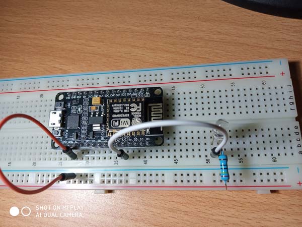
Schematics


Uploading the Sketch
If you are using an ESP-12E NodeMCU Kit, uploading the sketch (a program compiled with Arduino IDE) is very simple, since both programmer and USB port are part of this device.
Plug your board to your computer. In Arduino IDE, select Tools / Board / Node MCU 1.0 (in our case, unless you have a different one).
Select the port: Arduino IDE / Tools / Port.
Click the Upload arrow icon on top-left of Arduino IDE, and wait for your code to be compiled and uploaded to the chip.
The code (blinker.ino)
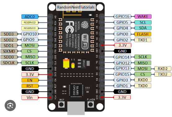
The code is self-explainatory. The only question is: how do we know, that Pin 2 (GPIO 2) is at D4? This link has pinouts for different types of boards: https://randomnerdtutorials.com/getting-started-with-esp8266-wifi-transceiver-review/

Troubleshooting
Sometimes, you get an error: "esptool.FatalError: Failed to connect to ESP8266: Timed out waiting for packet header". It means that your ESP8266 is not in flashing/uploading mode.
Make sure you have selected the right board name in the list provided by Arduino IDE. Then press and hold the "BOOT/FLASH" button in your ESP8266 board; press the "Upload" button in the Arduino IDE to upload your sketch.
As soon as you see the "Connecting..." message in your Arduino IDE, release the finger from the "BOOT/FLASH" button.