ESP8266 Examples: NodeMCU Web Server
In this post we will build an ESP8266 based Web Server and walk through both the code and schematics. This tutorial is a step-by-step guide that shows how to build a standalone ESP8266 Web Server that controls a single output (one LED). This ESP8266 NodeMCU Web Server is mobile responsive and it can be accessed with any device with a browser in your local network.
Please pay attention to the last statement: we are going to create a web server that works with your modem within your LOCAL network. It can not be seen from the outside Internet. So you can use this approach for your IOT projects, but can not post data to the Web (a different approach exists, it is just... different).

The Code
In the following code, replace placeholders for login and password with ones for your home WiFi network. Note, that your WiFi router has to have 2.4 GHz enabled (get to router's admin page and make sure it is on).
This is a close copy of https://randomnerdtutorials.com/esp8266-web-server/, except one diode is used instead of two.
/*********
Rui Santos
Complete project details at https://randomnerdtutorials.com
*********/
// Load Wi-Fi library
#include
// Replace with your network credentials
const char* ssid = "this_is_my_id";
const char* password = "this_is_my_password";
// Set web server port number to 80
WiFiServer server(80);
// Variable to store the HTTP request
String header;
// Auxiliar variables to store the current output state
String output2State = "off";
// Assign output variables to GPIO pins
const int output2 = 4;
// Current time
unsigned long currentTime = millis();
// Previous time
unsigned long previousTime = 0;
// Define timeout time in milliseconds (example: 2000ms = 2s)
const long timeoutTime = 2000;
void setup()
{
Serial.begin(115200);
// Initialize the output variables as outputs
pinMode(output2, OUTPUT);
// Set outputs to LOW
digitalWrite(output2, LOW);
// Connect to Wi-Fi network with SSID and password
Serial.print("Connecting to ");
Serial.println(ssid);
WiFi.begin(ssid, password);
while (WiFi.status() != WL_CONNECTED)
{
delay(500);
Serial.print(".");
}
// Print local IP address and start web server
Serial.println("");
Serial.println("WiFi connected.");
Serial.println("IP address: ");
Serial.println(WiFi.localIP());
server.begin();
}
void loop()
{
// Listen for incoming clients
WiFiClient client = server.available();
if (client)
{
// If a new client connects,
// print a message out in the serial port
// make a String to hold incoming data from the client
Serial.println("New Client.");
String currentLine = "";
currentTime = millis();
previousTime = currentTime;
// loop while the client's connected
while (client.connected()
&& currentTime - previousTime <= timeoutTime)
{
currentTime = millis();
// if there's bytes to read from the client
if(client.available())
{
// read a byte, then
// print it out the serial monitor
char c = client.read();
Serial.write(c);
header += c;
// if the byte is a newline character
if(c == '\n')
{
// if the current line is blank,
// you got two newline characters in a row.
// that's the end of the client HTTP request,
// so send a response:
if (currentLine.length() == 0)
{
// HTTP headers always start with a response code
// (e.g. HTTP/1.1 200 OK)
// and a content-type so the client knows what's coming,
// then a blank line:
client.println("HTTP/1.1 200 OK");
client.println("Content-type:text/html");
client.println("Connection: close");
client.println();
// turns the GPIOs on and off
if (header.indexOf("GET /2/on") >= 0)
{
Serial.println("GPIO 2 on");
output2State = "on";
digitalWrite(output2, HIGH);
}
else if (header.indexOf("GET /2/off") >= 0)
{
Serial.println("GPIO 2 off");
output2State = "off";
digitalWrite(output2, LOW);
}
// Display the HTML web page
client.println("");
client.println(
"");
client.println("");
// CSS to style the on/off buttons
// Feel free to change the background-color and
// font-size attributes to fit your preferences
client.println("");
// Web Page Heading
client.println("ESP8266 Web Server
");
// Display current state, and ON/OFF buttons for GPIO 2
client.println("GPIO 2 - State " + output2State + "
");
// If the output2State is off, it displays the ON button
if (output2State=="off")
{
client.println("");
}
else
{
client.println("");
}
client.println("");
// The HTTP response ends with another blank line
client.println();
// Break out of the while loop
break;
}
else // if you got a newline, then clear currentLine
currentLine = "";
}
// if you got anything else but a carriage return character,
// add it to the end of the currentLine
else if (c != '\r')
currentLine += c;
}
}
// Clear the header variable
header = "";
// Close the connection
client.stop();
Serial.println("Client disconnected.");
Serial.println("");
}
}
Click the Upload arrow icon on top-left of Arduino IDE, and wait for your code to be transfered to the chip.
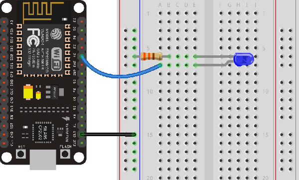
Parts required
ESP8266 NodeMCU
LED
Resistor (220 - 330 ohms should work just fine)
Breadboard
Jumper wires
Note that we use the same schematics as in blinker example.

Testing the Web Server
Now, you can upload the code, and it will work straight away. Don’t forget to check if you have the right board and COM port selected in Arduino IDE, otherwise you’ll get an error when trying to upload. Open the Serial Monitor at a baud rate of 115200.
Finding the ESP IP Address
Press the ESP8266 RESET button, and it will output the ESP IP address on the Arduino IDE's Serial Monitor. Alternatively, wait until connection succeeded: the address will be displayed in the monitor.
Accessing the Web Server
Open your browser, type the ESP IP address, and you’ll see the following page. This page is sent by the ESP8266 when you make a request on the ESP IP address.

Click the button: the LED diode goes on and off.