Multiple Analog Sensors with NodeMCU Web Server
ESP8266 is one of the most populat chips for Internet of Things programming. Unfortunately, it only has one analog pin (A0), which is not enough in case you want to read multiple sensors. A common solution ot this problem is using a multiplexer: it has multiple inputs and you call (programmatically, in real time) tell it which one to read, or to put it differently, which one to conect to its single output.
In this tutorial we are going to use 74HC 4051 - a 8 channels multiplexer.
In this example we are going to create a server that provides a web page. This web page is similar to previous example: it allows sending commands to 8266 (turn light dione on/off), and receives thermistor-provided themperature data. The difference is, we now have two thermistors (and can increase it up to eight), so we use a multiplexer.
Again, if we compare this example with the previous one, we can see that an analog pin A0 of ESP8266 is now connected to a multiplexer, instead of going directly to a sensor (thermistor).
A multiplexer "splits" this A0's "channel", so two pins (Y6 and Y7 in this example) are connected to it. Connected, of course, ONE AT A TIME, and which thermistor is being read at the moment, depends on the state of 3 command pins, S0, S1 and S2.
As in the previous example, thermistors are used together with the 10K resistor, forming a bridge.
Schematics
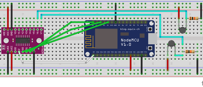
It might look complex, but the only difference between sketch and one from the previous tutorial is that thermistors are connected to A0 via a multiplexer, and not directly.
The code
First of all (again, as in a previous example), we keep HTML code for our web page in a variable, variable is stored in an index.h file, which is included in the main C++ file.
The code was inspired by Circuits4you.com, a site that is highly recommended.
index.h
const char MAIN_PAGE[] PROGMEM = R"=====(
<!DOCTYPE html>
<html>
<head>
  <link rel="icon" href="data:,">
</head>
<body>

<div id="demo">
<h1>The ESP8266 NodeMCU Update Sensors</h1>
  <button type="button" onclick="sendData(1)">LED ON</button>
  <button type="button" onclick="sendData(0)">LED OFF</button><BR>
</div>

<div>
  LED State is : <span id="LEDState">NA</span>
  <br>Thermistors: <span id="thermistors">NA</span>
  <br>
</div>

<table id="freezer_task" border=0>
</table>

<script>
function sendData(led)
{
  var xhttp = new XMLHttpRequest();
  xhttp.onreadystatechange = function()
  {
    if (this.readyState == 4 && this.status == 200)
    {
      document.getElementById("LEDState").innerHTML =
      this.responseText;
    }
  };
  xhttp.open("GET", "setLED?LEDstate="+led, true);
  xhttp.send();
}

setInterval(function()
{
  // Call a function repetatively with 2 Second interval
  getSensors();
}, 2000); //2000mSeconds update rate

function getSensors()
{
  var xhttp = new XMLHttpRequest();
  xhttp.onreadystatechange = function()
  {
    if (this.readyState == 4 && this.status == 200)
    {
      document.getElementById("thermistors").innerHTML = this.responseText;
    }
  };
  xhttp.open("GET", "read_sensors", true);
  xhttp.send();
}

</script>
<br>
</body>
</html>
)=====";
We had two choices here: we could create a separate request for each sensor, but for multisensor systems it would create a messy code. It is easier to pack two sensors' readings into a single string variable (it happens in a C++ code, see below) and to copy it in an HTML element called "thermistors". Note that if we want to do something with this data, like plotting a chart, we can always parse the string, which is much cheaper than creating extra requests.
Let's take a look at the Arduino code:
#include
#include
#include

// Include the HTML template
#include "index.h"

// On board LED that we control by pressing HTML buttons.
#define LED 2

Connections between NodeMCU and multiplexer
// 8266  ->  4051 multiplexer
// D4    ->   S0 (A)
// D3    ->   S1 (B)
// D2    ->   S2 (C)
// A0    ->   Common
// 3.3v  ->   VCC
// G     ->   GND
// G     ->   Inhibit
// G     ->   VEE

#define MUX_A D4
#define MUX_B D3
#define MUX_C D2
#define ANALOG_INPUT A0

// In this example I use 2 thermistors, on Y6 and Y7

//SSID and Password of your WiFi router
const char* ssid     = "this_is_my_id";
const char* password = "this_is_my_password";

ESP8266WebServer server(80); //Server on port 80

// ---

// NodeMCU on board 3.3v vcc
const double VCC = 3.3;

// 10k ohm series resistor
const double R2 = 10000;

// 10-bit adc
const double adc_resolution = 1023;

// thermistor equation parameters
const double A = 0.001129148;
const double B = 0.000234125;
const double C = 0.0000000876741;

// This code is executed when you open its IP in browser
void handleRoot()
{
	// Read HTML contents.
	// MAIN_PAGE is a variable defined in an include file
	String s = MAIN_PAGE;

	//Send web page
	server.send(200, "text/html", s);
}

// ---

double adcToTemperature(double dRawAdc)
{
  double Vout = (dRawAdc * VCC) / adc_resolution;
  double Rth = (VCC * R2 / Vout) - R2;

  //  Steinhart-Hart Thermistor Equation:
  //  Temperature in Kelvin = 1 / (A + B[ln(R)] + C[ln(R)]^3)
  //  where A = 0.001129148, B = 0.000234125 and C = 8.76741*10^-8

  // Temperature in kelvin
  double dTemperature = (1 / (A + (B * log(Rth))
	+ (C * pow((log(Rth)),3))));

  // Temperature in degree celsius
  dTemperature = dTemperature - 273.15;

  return dTemperature;
}

// ---

void handleSensors()
{
  double dRawAdc;

  // Multiplexer 7
  changeMux(HIGH, HIGH, HIGH);

  dRawAdc = analogRead(ANALOG_INPUT);

  // Temperature in degree celsius
  int nTemperature_7 = (int)adcToTemperature(dRawAdc);

  // Multiplexer 6
  changeMux(HIGH, HIGH, LOW);
  dRawAdc = analogRead(ANALOG_INPUT);

  // Temperature in degree celsius
  int nTemperature_6 = (int)adcToTemperature(dRawAdc);

  // ---

  Serial.print("Temperature = ");
  Serial.print(nTemperature_7);
  Serial.println(" and ");
  Serial.print(nTemperature_6);
  Serial.print(" degree celsius");

  String strTemperature = String(nTemperature_7)
	+ " and " + String(nTemperature_6) + " degree celsius; ";

  //Send ADC value only to client ajax request
  server.send(200, "text/plane", strTemperature);
}

void handleLED()
{
 String ledState = "OFF";
 //Refer  xhttp.open("GET", "setLED?LEDstate="+led, true);
 String t_state = server.arg("LEDstate");
 Serial.println(t_state);
 if(t_state == "1")
 {
  digitalWrite(LED,LOW); //LED ON
  ledState = "ON"; //Feedback parameter
 }
 else
 {
  digitalWrite(LED,HIGH); //LED OFF
  ledState = "OFF"; //Feedback parameter
 }

 //Send web page
 server.send(200, "text/plane", ledState);
}

// --- Handling multiplexing of one A0 analog input to few sensors
void changeMux(int c, int b, int a) {
  digitalWrite(MUX_A, a);
  digitalWrite(MUX_B, b);
  digitalWrite(MUX_C, c);
}

//==============================================================
//                  SETUP
//==============================================================
void setup(void){
  Serial.begin(115200);

  //Connect to your WiFi router
  WiFi.begin(ssid, password);
  Serial.println("");

  //Onboard LED port Direction output
  pinMode(LED,OUTPUT);

  // --- Handling multiplexing of one A0 analog input to few sensors
  pinMode(MUX_A, OUTPUT);
  pinMode(MUX_B, OUTPUT);
  pinMode(MUX_C, OUTPUT);

  // Wait for connection
  while (WiFi.status() != WL_CONNECTED) {
    delay(500);
    Serial.print(".");
  }

  //If connection successful show IP address in serial monitor
  Serial.println("");
  Serial.print("Connected to ");
  Serial.println(ssid);
  Serial.print("IP address: ");

  //IP address assigned to your ESP
  Serial.println(WiFi.localIP());

  //Which routine to handle at root location. This is display page
  server.on("/", handleRoot);
  server.on("/setLED", handleLED);
  server.on("/read_sensors", handleSensors);

  server.begin();                  //Start server
  Serial.println("HTTP server started");
}

//===

void loop(void)
{
  server.handleClient();          //Handle client requests
}
To run this example, connect th eESP8266's USB to your PC, compile and upload the Arduino program. Make sure your modem's WiFi is on and support for 2.4G is checked in modem settings.
When the connection is established, the IP address will be displayed in the Arduino's Monitor. Copy it and open that page in your browser. You will see the web page:
