Measuring pulse with MAX3010X family
First of all, MAX3010X is one of the cheapest and as the result, of the most popular pulse measuring chips. Big mistake. Below I am going to show the basics, but those chips are NOT RECOMMENDED, unless you want to spend some quality extra time soldering.
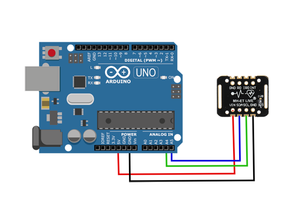
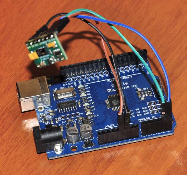
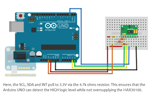
Ok, let's create a simple Arduino or ESP8266 based model:


Here is the code:
Max30100, Max30101 and Max30102 are I2C pulse meters based on red and IR diodes. Connecting is very simple: all we need is to provide power (5V) and connect two digital pins (of Arduino, ESP8266 or some other controller) to SCL and SDA pins. The resolution of a sensor is sufficient to provide a nice cardiogram. The code below reads it and sends the result to serial port, you can watch readings in Arduino's Serial Terminal or Serial Plotter.
#include
#include "MAX30105.h"

#include "heartRate.h"

MAX30105 particleSensor;

const byte RATE_SIZE = 4; //Increase this for more averaging. 4 is good.
byte rates[RATE_SIZE]; //Array of heart rates
byte rateSpot = 0;
long lastBeat = 0; //Time at which the last beat occurred

float beatsPerMinute;
int beatAvg;

void setup()
{
Serial.begin(115200);
Serial.println("Initializing...");

// Initialize sensor
if (!particleSensor.begin(Wire, I2C_SPEED_FAST)) //Use default I2C port, 400kHz speed
{
Serial.println("MAX30105 was not found. Please check wiring/power. ");
while (1);
}
Serial.println("Place your index finger on the sensor with steady pressure.");

particleSensor.setup(); //Configure sensor with default settings
particleSensor.setPulseAmplitudeRed(0x0A); //Turn Red LED to low to indicate sensor is running
particleSensor.setPulseAmplitudeGreen(0); //Turn off Green LED
}

void loop()
{
long irValue = particleSensor.getIR();

if (checkForBeat(irValue) == true)
{
//We sensed a beat!
long delta = millis() - lastBeat;
lastBeat = millis();

beatsPerMinute = 60 / (delta / 1000.0);

if (beatsPerMinute < 255 && beatsPerMinute > 20)
{
rates[rateSpot++] = (byte)beatsPerMinute; //Store this reading in the array
rateSpot %= RATE_SIZE; //Wrap variable

//Take average of readings
beatAvg = 0;
for (byte x = 0 ; x < RATE_SIZE ; x++)
beatAvg += rates[x];
beatAvg /= RATE_SIZE;
}
}

Serial.print("IR=");
Serial.print(irValue);
Serial.print(", BPM=");
Serial.print(beatsPerMinute);
Serial.print(", Avg BPM=");
Serial.print(beatAvg);

if (irValue < 50000)
Serial.print(" No finger?");

Serial.println();
}
For the code to run you need to install the MAX library:
In the Arduino IDE:
Go to Sketch -> Include Library -> Manage Libraries
Type in "max30" into the search bar
Download the "Sparkfun MAX3010x Pulse and Proximity Sensor Library"
Looks like all is done... and it simply doesn't work! Here is why:
http://bobdavis321.blogspot.com/2021/02/working-with-max30100-and-max30102.html
https://reedpaper.wordpress.com/2018/08/22/pulse-oximeter-max30100-max30102-how-to-fix-wrong-board/
https://www.teachmemicro.com/max30100-arduino-heart-rate-sensor/
Let me duplicate the explanations in case links go dead.
There is a critical error in a chip's schematics. It uses two voltage regulators, and one that is 1.8V, is not working. Resistors used with it do not pull nything anywhere and as the result, the diode is off, and the chip is not recognized by Arduino.
Here are two ways to fix it (again, copied from exellent sources quoted above, just in case):
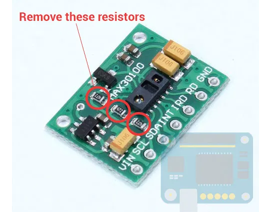
1. Cut the line (red cross on the image below) and connect two points as the yellow line shows.

2. Remove (unsolder) resistors and use external ones:
After all those fixes, you have 50/50 chances that everything will work.
Here is why (quoting the excellent https://reedpaper.wordpress.com/2018/08/22/pulse-oximeter-max30100-max30102-how-to-fix-wrong-board/):
What do you think the Chinese did when they found out that they manufactured a billions boards with an error? Sit straight and breathe deeply. Instead of throw the wrong boards in the trash they decide to install on the board the regulator with 2.8V output voltage! It's a vile blow to the back of a radio amateur - I can not call it otherwise. With this supply voltage the I2C bus normally works with 5V TTL Arduino boards. At first glance all going well. The module seems to be working and even measuring something. However, for the MAX3010x this voltage is far beyond the permissible range.
No, the sensor does not completely fail but make a measures mostly wrong. The MAX30100 Datasheet clearly states that compliance with the power range is necessary for the stable operation of the built-in counter (referring to the built-in timing block for the ADC and logic timers). As a result, we are surprised to find that a professional-level sensor works extremely unstable and is not at all as described in Internet articles. I spent the whole evening to understand what was going wrong.
Final fix
Measure the voltage at the output of the second regulator. If there is + 1.8V then you are lucky. After cutting the track and installing the jumper the procedure is complete. Otherwise you will have to replace the regulator. We need a regulator XC6206P182MR. You can try to order it in your local store. But somewhere it may be easier and cheaper to order regulator on Ebay or Aliexpress. On Aliexpress a lot of 100 regulators are offered for $1.70. Be careful while ordering! Two digits after the letter P denote the operating voltage. In our case 18 means 1.8V.
Remove the wrong 2.8V regulator, cut the track, put the jumper, install 1.8V regulator on his place. Now that's all!
As I mentioned, this sensor is not recommended: there are reasonable alternatives out there.