Cycloidal reductor
Introduction
When we design robotic arm, we face a rather standard challenge. Motors usually spin very fast, and "fast" also comes with
"low torque". A common NEMA-17 has something arouns 1kg/cm, which means 10 g/m. In other words, robotic arm that uses
NEMA-17 - and it is a good motor - that is 1 meter long will be able to lift 10 grams.
But in the same time NAMA-17 can go as fast as 300 rpm. So by reducing it to 1 rpm, we will have 300g/meter,
which is much better. If we make our robot smaller, with 0.5 m arms, it makes 600 g load, so your robot
will be able to pass you a cup of tea. But not a beer bottle, as this 600g include the weight of the hand itself...
As you can see, reductors are important.
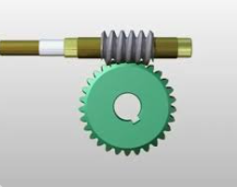
And of course, there are many modifications of them. Here is the simplest one:
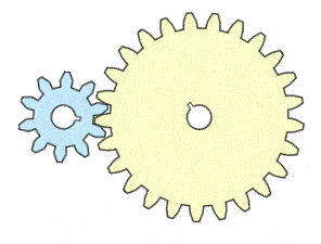
Small gear spins fast and large gear spins slow, but with larger torque. Two problems though. First, in an example above we used 1:300 reduction. We can not (or at least should not) do it with a single pair of gears. Second problem is more important. The contact between gears is just one small piece of metal, and provided high torque, it will easily break.
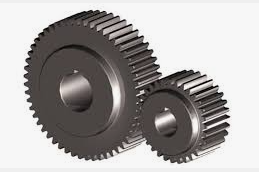
First problem can be solved by increasing size of the contact area (making gears thick):
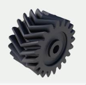
In extreme cases, we use herring bone gears:
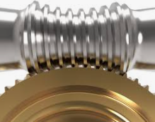
Second problem can be solved by using worm gears:
There are additional technical tricks to increase contact area, just one example (Notice the shape of the "worm"):
Still, cycloidal reductor is better, especially if we expect spikes in load, for example, when something heavily falls on our robot's arm. Plus we can easily achieve signifficant reduction - one that would otherwise require multi step reductors (well, maybe except for worm gears).
But it is, by all means, not the only option we have.
I am not going to explain how this thing works: there are thousands good introductions online. Instead, I am going to focus on practical implementation. Because... Because, as usual, people would show you the end result, but will not tell "little things", and without knowing those, you will fail, even if you have STL files.
STL files for the reductor are part of an archive.
Choosing reductor model
Cycloidal reductors are wildly popular. As the result, there are many versions of them. Some use bearings. Some do not. Seriously. You get the motor-ready reductor from thingiverse.com, and it doesn't use bearings. At 300+ rpm plastic will melt, so this device's life will be seconds, not years.
Some are two step reductors. Those are nice ones, and yes, they work. But they are harder to print, as higher accuracy is required.
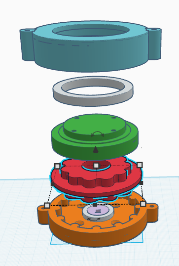
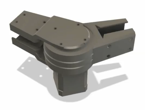
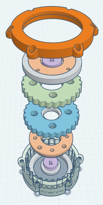
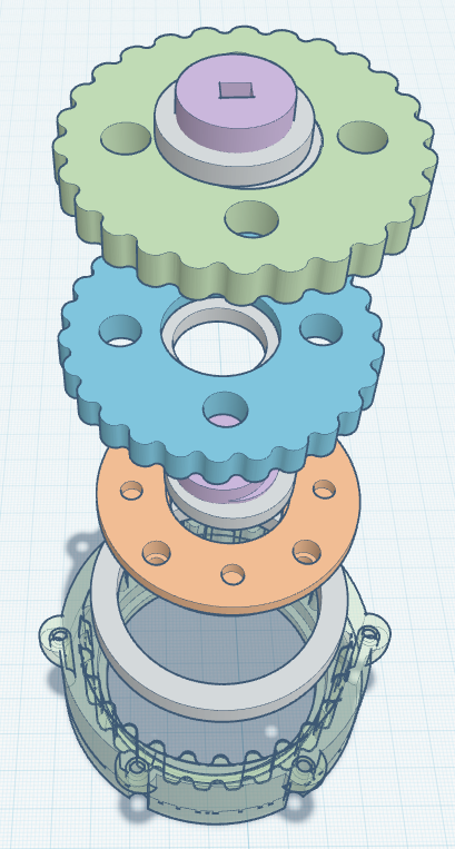
Let's spend some time and try to understand how the double step reductor on the image above works. First of all, the pale magenta part with assymetric hole. This is where the motor is attached.
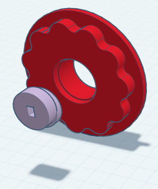
The "pale magenta" part has two disks, one shifted relative to another. So the red part (on the same image) moves by cycloidal trajectory. And there, on the side of the red part that is facing us, we see the gear responsible for the first step.
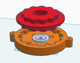
On the image above, the brown part is the outer gear that remains steady while the red part's firth step gear (facing down on the image) "walks" around it. On the same image you can see that red part also has a second step gear (facing up) and a disk that separates them.
The separating disk sits on top of the brown part, all it does is preventing the red part from falling too deep into the brown part. This is a simple and obvious solution, but it is also suboptimal: there will be a lot of friction. In a more "industrial" designs (let me repeat, there are literally thousands of versions) you might see bearings used to reduce friction.
And speaking of friction. Most 3d printed designs you will find online have this problem: plastic does not handle friction very well, especially if it is used at high rpm. It melts. Keep that in mind.
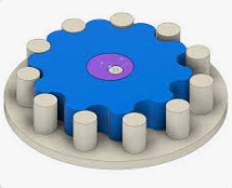
Ok, so far we have the first step gear "walking" inside the brown part's gear. As the second step's gear is attached to first step gear, it moves in the similar way. All we need to do now is to add second "outer" gear, and the second step's gear of the red part will make it spin. And as we use proper number of vaves on each step... it will rotate slower, so speed will drop on both first and second steps:
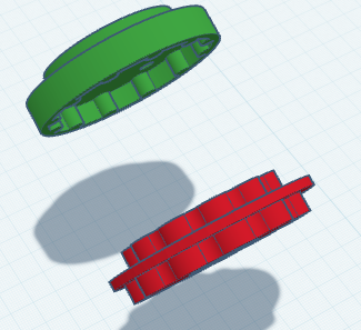
On the image above, you can see the green part that has inner 2nd step's gears.
Let's summarize: let's say we have brown part with 1st step's outer gear, 12 vaves. Then the red part's 1st step's inner gear should have 11 vaves, and it will rotate 11 times slover.
Then the red part's 2nd step's gear should have same 11 vaves, while green part's gear should have 10 vaves, and so 2nd step will produce 10 times slower rotation. Total reduction is 10 * 11 = 110 times.
Now, please keep in mind that the device we just examined is not trying to rotate rears, instead, it pushes them towards each other in a sideways manner. This pressure is transformed into rotation... If parts can not move sideways. If they can, they will simply move, and there will be no rotation.
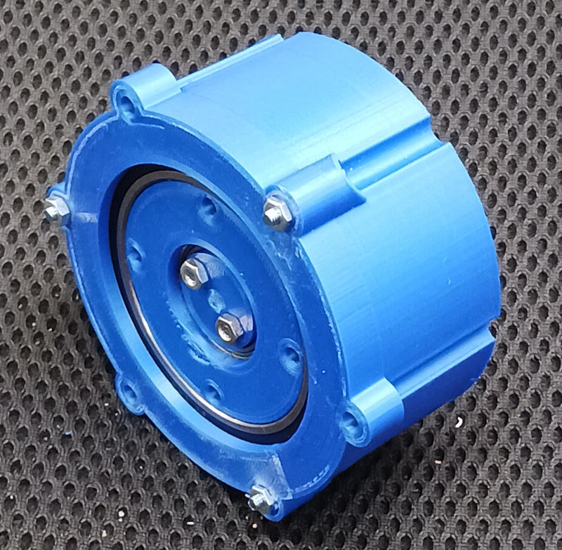
So we have to make sure the green part (which is our reductor's "output" can rotate but can not move sideways. We add the bearings (see white ring on top of green part):
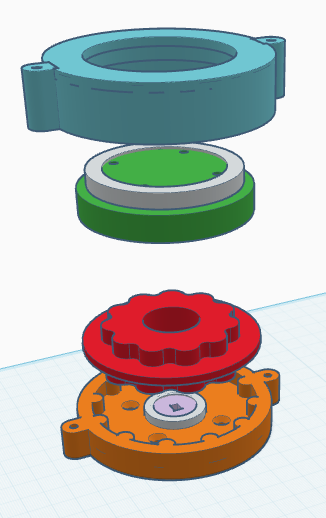
Finally, we need to fix the bearing and make sure it does not move sideways relative to the reducer's "input". In other words, we need the outer body of the device (light blue part on the image above).
Ok, this was one of many designs. Some are much more complex.
Some use flexible gears. This approach makes it much easier to make, but friction is higher (some models solve this problem) and I am not sure how they handle high torque.
And so on. As I said, cycloidal reductors are very popular and have many modifications. Also, if we focus on robotic joints, there are different ways of attaching them to the, well, rest of the robot. Compare:
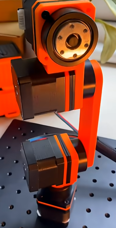
Here the "rest of the arm" is attached to the side of a joint. And it will work... as long as you do not tilt your robot, which will create a "dislocating" force which, at some point, will break it (sideways).
Compare:
Here the joint is protected from both sides, and dislocating it is much harder. Note that the design is pretty much the same with some minor differences. But in one case we have the side that is rotating, and in the other case the middle part rotates.
So I am going to choose the later model. It is simple to make, solid and has about 10x reduction rate. And if you need more... I will show you how to easily chain these reductors.
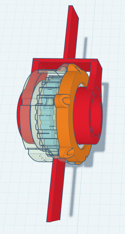
On the image above you can see that on each side of the reductor there are 4 holes. There we can attach the Y-like "bone" of our robotic arm, so the cylinder of reductor is between left top and right top parts of this "Y". Also, we can attach a motor (holes are for NEMA-17) to these holes - on top of the "Y".
Side vs middle part rotating
As I mentioned earlier, we can, using the same design, make either side of our assembly or its middle part rotate. Let's walk through this magic. Well... As with any magical trick, the keyword here is "trick". Here we go:
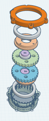
On the image above we see the reductor I am going to build. It is a simple one step reductor with 25x reduction ratio. And as it is a one step reductor, it is... symmetric! It means that it does not mater to which side you will attach the motor. On the following image, the magenta part (where the motor is going to be attached) is duplicated on the other end of a reductor.
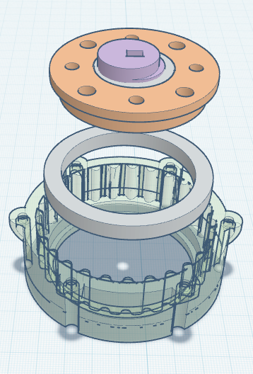
So if we look at the end (no mater which one) of the device, we see this:
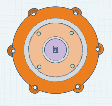
A magenta part in the middle is where we attach the motor. We make this part spin. Then there is a small white ring: the bearing. Then the "salmon color" part, this is the "output" of our reductor, it spins with lower speed but higher torque. Then there is a large white ring: another bearing. And the brown part is the body.
Think about it: we attach the motor's shaft to magenta part and turn the motor on. If the motor's body is attached to "salmon" part, then the body (brown part) will rotate. And if we attach motor to brown part, the "salmon" part will rotate. That's all!
Think about it this way: when you turn on the motor while holding motor's body, shaft rotates. But if you hold the shaft, then a motor will rotate around it. The only difference in our case is, we add reductor, so rotation is slower.
One step reductor design
Let's walk through the design of a reductor, step by step.
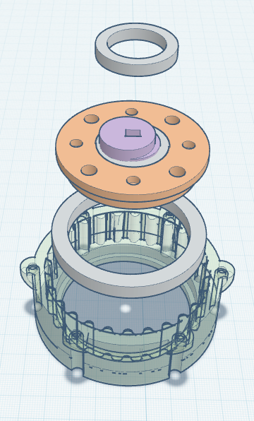
First, the base.
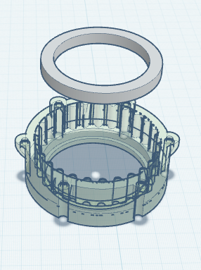
This is the outer hull of a reductor, that holds everything in place, plus, its inner surface has valves the rotor will be "walking" over.
Also at the image above you can see a 62 mm bearing.
Next, the "magenta part" and a small (27 mm) bearing holding it.
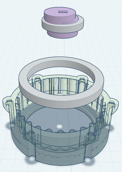
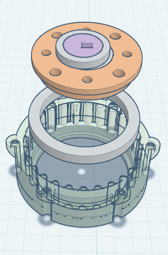
The magenta part is made of two cylinders, one is centered with bearing, shaft of the motor and the reductor's body, while the second cylinder is shifted. So, when we turn on the motor, the shifted cylinder will Make the gear (see below) rotate in an excentrical way.
As I mentioned, the magenta part is being held in place by a small bearing, which in turn, is fixed by "salmon color" part. Note that as the result, "salmon" part is locked between two bearings, it can spin, but it will ignore any forces that are directed sideways.
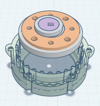
Now we put a second small bearing on the shifted cylinder of a magenta part. See, we are going to make the magenta part spin excentrically inside the hole in a gear (see below). But without a bearing, it will get a lot of friction. As magenta part is the one attached to the motor, it is the fastest spinning part of our device, so we need to make sure friction is low.
Once again, salmon part is locked between two bearings:
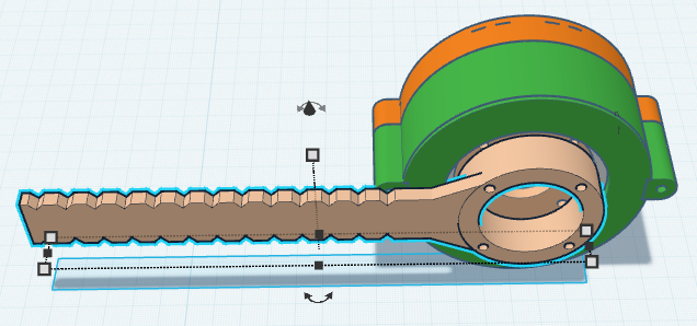
Now, the gear itself. Actually, we have two of them. The reason is, it will make the reductor more stable to slippage and to breaking as well. Note, however, that one gear is enough.
Note that each of two gears has its own magenta part and a small bearing. And these two magenta parts are turned 180 degrees relative to each other. So the blue gear is shifted left, while green gear is shifted right. They get support against opposite sides of the outer gear (one on the inner side of the reductor's body). This is exactly why I mentioned that using Two gears makes the device more stable.
Note that two gears are moving relative to each other, so there be some friction. There are few solutions that allow us to reduce this friction, but I am not going to address it: gears move just a little and friction doesn't do any real damage, like overheating or wearing off.
Note again that our reductor is symmetric.
Using reductor as a robotic joint
This is a rather simple part: we add "bones" to our joint. As in a human body, "bones" should be attached on the opposite side of a joint, to the parts of a joint that move relative to each other. On the following inage I used red color for such bones: